Remote controllers – Allen&Heath iDR-Switch User Manual
Page 4
4
IDR-switch User Guide AP5141
Remote controllers
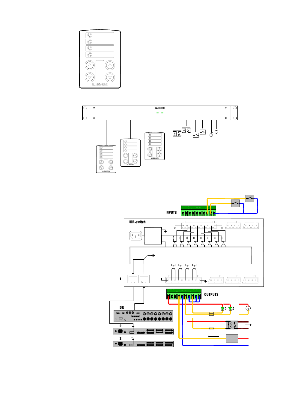
The iDR-switch is designed to be
used with a wide range of remote control devices including
custom wall plates and operator panels. Check out the Allen &
Heath range of PL wall plates and remote controllers. This
range is continually developing and it is likely that some may
be suitable for your application.
At the time of print of this user guide the PL-2 wall plate is
available for use with the iDR-switch. It has 4 switches and 4
3-colour LEDs which can be hard wired to the unit. It can be
fitted into a UK or US standard single wall box. For further
details visit the Allen & Heath web site.
link
power
24 IN 16 OUT SWITCH CONTROLLER
iDR-switch
iDR-switch
Switch closures
Open-collector logic
Relays
Lamps
Connectors:
Pluggable Phoenix 10way terminal
Mating screw terminal plugs provided
Switch Inputs:
24x switch closure inputs
Opto-isolated via 2k2 from +10V
Switch closure connects pin to ground (5mA)
Switch cable resistance up to 1k ohm
Logic Outputs:
16x logic outputs
Opto-isolated open-collector
Floating collector (+) and emitter (-) pins
Internal 10V DC source (500mA total max)
External DC source (+24V 200mA each max)
Communication:
DR-link serial port using RJ45 connectors
Uses Allen & Heath DR-link protocol
2m CAT5 STP cable supplied, max 300m
Daisy chain up to 3 units
Configuration:
Configure with iDR System Manager
operating software
Separately configure switches and output
Latched, press, release, time of day action
Power Supply:
Universal mains input 100-240V.AC
Independent 10V supply for connections
500mA total available
Dimensions:
Rack
483 x 144 x 44 mm (1U)
19’’ x 5.7’’ x 1.7’’
Desk
443 x 144 x 48 mm
17.4’’ x 5.7’’ x 1.9’’
Allow 75mm 3’’ for connectors
Weight 2.2kg 5lbs
+10V
G
20 19 18 17
G
21
22
23
24
V
+ -
G
13
+ -
14
+ -
15
+ -
16
GROUND
OUT
IN
DR-LINK
DC REFERENCE
VOLTAGE
INTERNAL POWER
9-16
1-8
9-12
5-8
1-4
+10V
2K2
SWITCH 25-48 OUT 17-32
SWITCH 49-72 OUT 33-48
CONTROL
CHAIN
OPTO-ISOLATED SWITCH INPUTS 1-24
OPTO-ISOLATED LOGIC OUTPUTS 1-16
V
+ -
G
+ - +
14
13
LED INDICATORS
RELAYS
+
-
+10V (or external supply)
+
CURRENT SINK
+V (+24V DC max)
GROUND
EXTERNAL POWER SUPPLY
DEVICE
200mA max
SWITCH
SWITCH
+10V DC INTERNAL POWER SUPPLY
LAMPS
MOTORS
EQUIPMENT
OPEN COLLECTOR
suitable resistors
+ -
15
isolated
LOW VOLTAGE
BULBS