Allen&Heath iDR-Switch User Manual
Idr-switch expander, Ap5141, User guide
iDR-switch User Guide AP5141
1
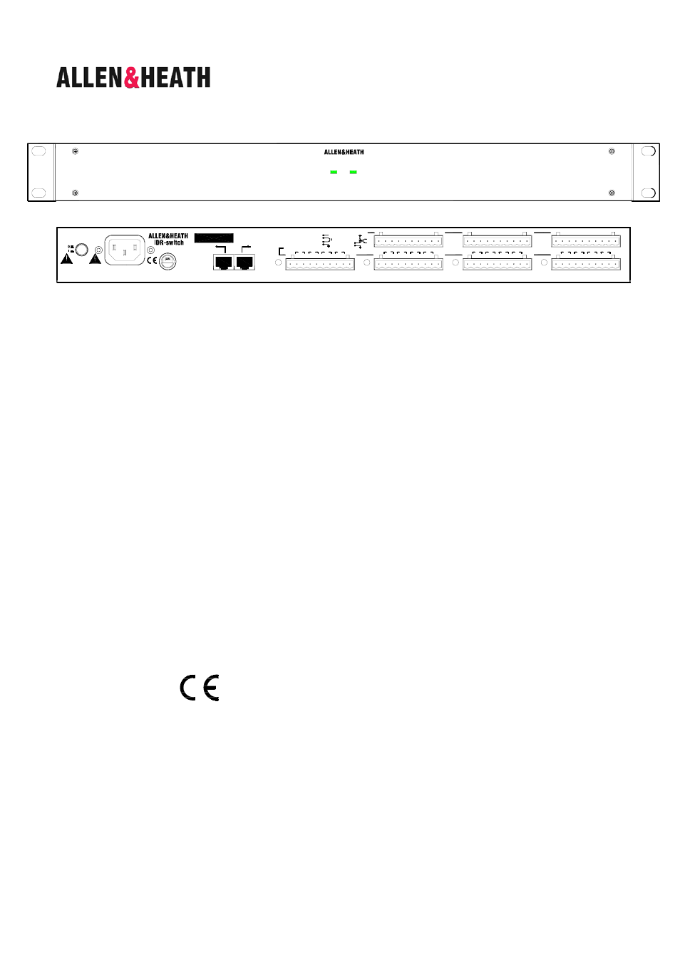
The iDR-switch is an add-on control expander for the iDR-8 audio mix processor. It provides an additional 24 switch
closure control inputs and 16 logic control outputs in a 1U high rack or desk mount case. Up to three units can be
connected providing up to 72 additional switch and 48 additional logic controls. These can be custom wired by the
installer to allow external equipment to control pre-determined mixer functions, or the mixer to control external
equipment. Typical applications include room wall plates for local volume control and source selection, patch recall,
logic control, automatic control of room dividers, projection screens, media players, lamps and other equipment.
The inputs and outputs are opto-isolated to avoid problems with equipment interaction. Grounding the switch inputs
using simple contact closures triggers the programmed function. The logic outputs are open collector and can be
wired to use the internal reference voltage or an external power supply. These typically drive LED indicators, filament
bulbs, relays and circuit logic. Wiring the interface should be carried out by competent installation personnel. The
switch and output functions are easily programmed using the iDR System Manager software.
The iDR-8 communicates with the iDR-switch via the DR-Link port. This uses the proprietary Allen & Heath DR-Link
protocol. A standard 2 metre CAT5 STP cable is provided. However, you can use a cable up to 300 metres long
letting you position the unit closer to the local switch wiring. A pass through connection lets you network up to three
units by daisy chaining them.
Plan the system
Before starting make sure you have planned how the
system is to work. Allocate the switch inputs and logic outputs and keep a log
of their intended function. Use the iDR System Manager software to configure
the system. Simulation windows are provided for you to try out your settings
without access to the units themselves. Refer to the Help file that comes with
the iDR System Manager software for details on how to assign the switch
inputs and logic outputs.
This product complies with the European Electromagnetic
Compatibility directives 89/336/EEC & 92/31/EEC and the
European Low Voltage Directives 73/23/EEC & 93/68/EEC.
NOTE: Do not remove the cover of the iDR-switch unit. There are no user
serviceable parts inside. Any changes or modifications to the equipment not
approved by Allen & Heath could void the compliance of the equipment and
therefore the users authority to operate it.
iDR-switch User Guide AP5141 Issue 2
Copyright © 2002 Allen & Heath Limited. All rights reserved
Whilst we believe the information in this guide to be reliable we do not assume
responsibility for inaccuracies. We also reserve the right to make changes in
the interest of further product development.
iDR-switch EXPANDER
AP5141
User Guide
link
power
24 IN 16 OUT SWITCH CONTROLLER
iDR-switch
V
G
G
4
3
2
1
G
5
6
7
8
G
12 11 10 9
G
13
14
15
16
G
20 19 18 17
G
21
22
23
24
SWITCH INPUTS
LOGIC OUTPUTS
1
2
3
+
-
4
V
G
V
G
V
G
+ - + - +
-
5
6
7
+ -
8
+ - + - + -
9
10
+ - + - + - + -
11
12
14
+ - +
- + - + -
15
16
13
switch
G
opto
+10V
2K2
opto
+
-
V
G
+10V DC max total 500mA
open collector
+24V DC, 200mA max
+10V
FUSE: T500mAL
WARNING
THIS APPARATUS MUST BE EARTHED.
ATTENTION: REMPLACER LE FUSIBLE AVEC UN DES MEMES CARACTERISTIQUES.
FOR CONTINUED PROTECTION AGAINST RISK OF FIRE REPLACE FUSE WITH SAME TYPE AND RATING.
100 - 240V~
47-63Hz ~ 15W MAX
CAUTION: RISK OF ELECTRIC SHOCK. DO NOT OPEN. AVIS: RISQUE DE CHOC ELECTRIQUE - NE PAS OUVRIR.
Made in the UK by ALLEN&HEATH LIMITED
Complies with UL6500, CSA-E65, EN60065
OUT
IN
DR-LINK
next
previous