Turning the expander on or off, Connecting to the idr-8, Connectors and grounding – Allen&Heath iDR-Switch User Manual
Page 2: Link power
2
IDR-switch User Guide AP5141
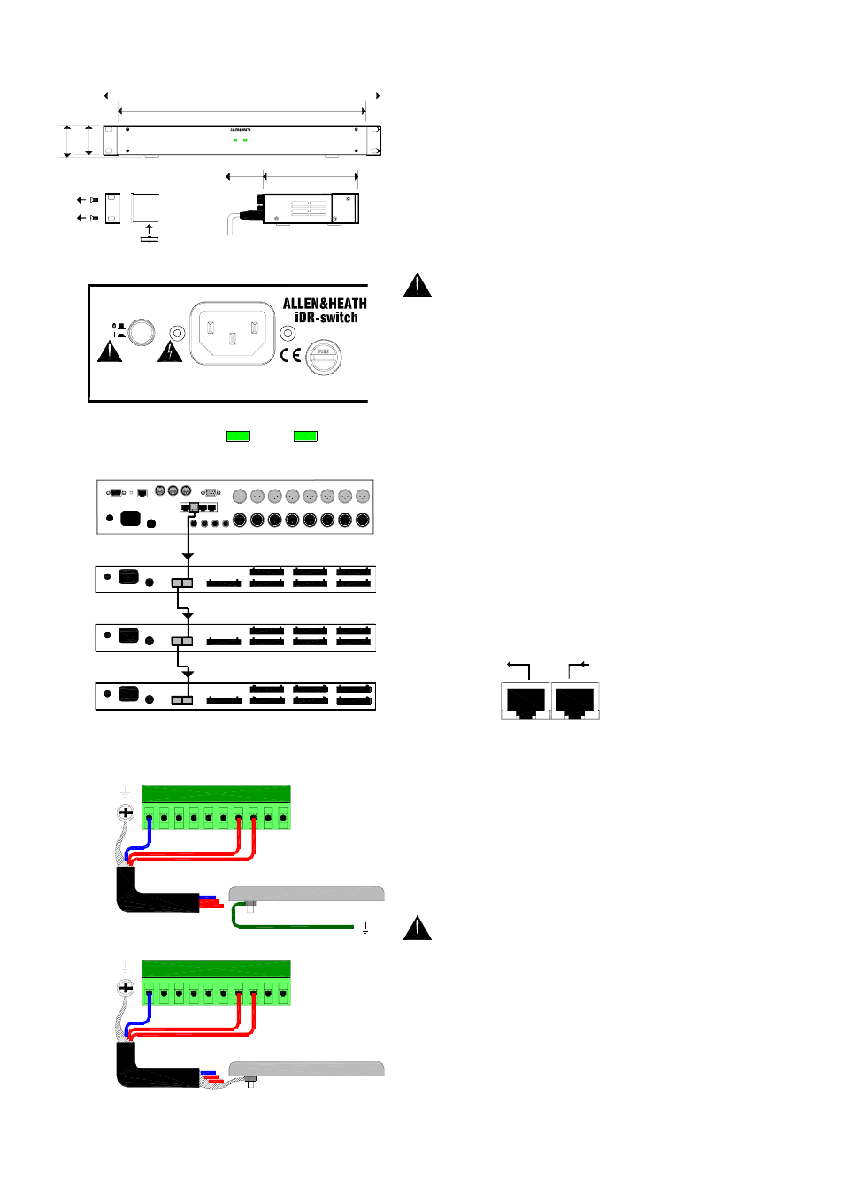
The iDR-switch can be rack mounted or free standing. There
are no user controls on the front panel. Allow a minimum of
65mm clearance behind the unit for the connectors and cables.
Ensure adequate ventilation to the side of and behind the unit.
It is shipped with its rack ears fitted and its feet removed ready
to be mounted in a standard 19” equipment rack. 1U rack
space is required. For desk mount operation remove the two
rack ears using a Torx (star head) T10 screwdriver. Fit the four
plastic feet provided by pressing them into the underside.
Make sure you have read the Safety Instructions
Sheet AP3345 which comes with the unit. Check that your
local mains supply is compatible with that printed on the
rear panel of the unit. Ensure that the correct mains lead
with moulded plug and IEC connector has been supplied.
For your own safety and optimum performance make sure
the system is correctly grounded.
Turning the expander on or off
Turn the unit on
by pressing the rear panel power ON/OFF switch. The power
LED lights up. The link LED lights if the DR-Link connection is
established with the iDR-8.
Connecting to the iDR-8
The iDR-8 communicates
with the iDR-switch using the DR-Link port. This serial
connection can be daisy chained through the 3 switch units as
shown, and then on to the iDR-in and iDR-out expanders if
fitted. Make sure you plug the DR-Link IN and OUT sockets
correctly. Use CAT5 STP cables with RJ45 connectors. Do not
use UTP cable. A standard 2 metre cable is provided with each
unit. You can use cables up to 300 metres long between units
for remote positioning. Ensure a good mains supply and solid
grounding to each unit.
Connectors and grounding
Pluggable Phoenix
type screw terminal connectors are used for connecting the
external switches and logic to the iDR-switch. Mating plugs
are provided with the unit. Make sure the wire ends are
carefully stripped and inserted into the terminals. Tighten the
screws using the correct slotted screwdriver. To ensure
interference-free operation use shielded cable. Connect the
shields to the chassis ground screw terminals provided next to
each connector. Fit the screws with the shake proof washers
provided.
For operator safety make sure that wall plates and
other control surfaces made from metal are correctly
bonded to ground (earth).
Strap the metal plate to the local ground at the wall box. For
ground isolation between the wall plate and equipment rack
connect the cable shield at the iDR-switch end only.
If a local ground is not available then use the cable shield to
connect the plate to the chassis of the iDR-switch unit as
shown. This is not necessary if the wall plate is made of non-
conductive material such as plastic which insulates it from the
operator.
SWITCH 49-72 OUT 33-48
DR-Link
SWITCH 1-24 OUT 1-16
SWITCH 25-48 OUT 17-32
G
METAL WALLPLATE
CHASSIS EARTH
G
METAL WALLPLATE
LOCAL EARTH BOND
link
power
FUSE: T500mAL
WARNING
THIS APPARATUS MUST BE EARTHED.
ATTENTION: REMPLACER LE FUSIBLE AVEC UN DES MEMES CARACTERISTIQUES.
FOR CONTINUED PROTECTION AGAINST RISK OF FIRE REPLACE FUSE WITH SAME TYPE AND RATING.
100 - 240V~
47-63Hz ~ 15W MAX
CAUTION: RISK OF ELECTRIC SHOCK. DO NOT OPEN. AVIS: RISQUE DE CHOC ELECTRIQUE - NE PAS OUVRIR.
OUT
IN
DR-LINK
next
previous
link
power
24 IN 16 OUT SWITCH CONTROLLER
iDR-switch
144mm
5.7"
209mm
8.2"
65mm
2.6"
48mm
1.9"
44mm
1.7"
1U
Remove 2x rack ears
Fit 4x feet
M3 Torx T10
483mm
19"
443mm
17.4"
iDR-switch