Using the switch closure inputs, Using the logic outputs – Allen&Heath iDR-Switch User Manual
Page 3
iDR-switch User Guide AP5141
3
Important Note:
The iDR-switch provides contact closure switch inputs and
open-collector logic outputs. How these are wired to external equipment is the
responsibility of the installer. Specification details are provided here for the iDR-switch
inputs and outputs. It is important that the installer is suitably qualified and familiar with
external control circuits to be able to work within the capabilities of the unit. Allen & Heath
do not assume responsibility for any damage done to the unit due to incorrect or faulty
connection to external equipment.
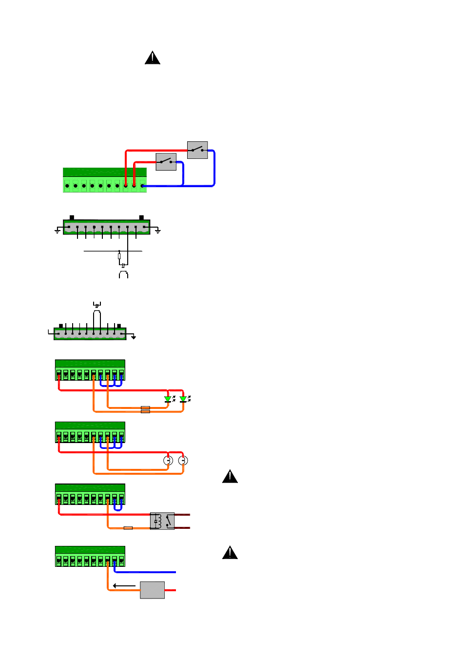
Using the switch closure inputs
The input is
opto-coupled to isolate the iDR-switch from the connected
equipment. It is switched by linking its connector pin to the
ground (‘G’) pin. Use a contact closure such as a momentary
press switch to do this.
The input pin is fed from the internal +10V reference supply
through a 2k2 ohm resistor. Around 5mA maximum current
flows when connected to ground. Combined switch and cable
resistance should not exceed 1k ohm for the switch to activate.
Each 10way connector provides 8 switch inputs. Either pin 1 or
pin 10 ‘G’ may be used as the common switch ground. One
cable can feed this ground to a bank of switches. Two are
shown in the diagram here. Do not use the chassis ground
screw which is for cable shielding and safety earthing only.
For reliable operation we recommend the use of heavy duty
sealed switches.
Using the logic outputs
Each output is opto-
coupled to isolate the iDR-switch from the connected
equipment. It provides an open collector output with floating
collector (+pin) and emitter (-pin).
Each 10way connector provides 4 open collector pairs as well
as an internal +10V DC supply and ground pins. Do not use
the chassis ground screw which is for cable shielding and
safety grounding only.
The output may be used in many ways to satisfy a wide range
of interfacing applications. It is important that the installer has
a good working knowledge of open collector and interfacing
circuits. Incorrect application may result in damage to these
outputs.
The internal +10V supply may be used as the power source for
low current applications such as turning on LEDs, lamps and
small relays. One cable can feed the common supply or
ground to a bank of outputs.
Maximum current drawn from the +10V supply for all
outputs combined must not exceed 500mA. Care must be
taken in component choice to ensure each operates within
its specified capability.
For higher current or voltage applications an external DC
power supply may be used. This also provides total isolation
between the iDR-switch and external equipment.
Maximum external supply voltage must not exceed
+24V DC. Maximum current sink through any open
collector output must not exceed 200mA.
A few examples are shown in the diagram here. For further
advice contact Allen & Heath technical support.
V
+ -
G
+ - +
2
1
LED INDICATORS
+10V DC
SUITABLE RESISTORS
+ -
3
V
+ -
G
+ - +
6
5
+ -
7
+ -
4
+ -
8
V
+ -
G
+ - +
10
9
+ -
11
+ -
12
V
+ -
G
+ - +
14
13
+ -
15
+ -
16
+10V
OPEN COLLECTOR
OPTO
INTERNAL DR-switch CIRCUIT
(1 OF 4 SHOWN)
LOW CURRENT 12V BULBS
LOW VOLTAGE RELAY
+
-
TO EQUIPMENT
SUITABLE RESISTOR
+10V DC
+10V DC
V
-
G
+
V
-
G
+
-
+
V
-
G
+
CURRENT SINK
+V (+24V DC max)
GROUND
EXTERNAL POWER SUPPLY
DEVICE
200mA max
SWITCH
SWITCH
4
3
2
1
5
6
7
8
G
G
12 11 10 9
13
14
15
16
G
G
20 19 18 17
21
22
23
24
G
G
INPUTS
2K2
+10V
OPTO
INTERNAL DR-switch CIRCUIT
(1 OF 8 SHOWN)