System function, Gr2 user guide, Configuration settings – Allen&Heath GR2 PL-12 USER GUIDE 1 User Manual
Page 9: Mic priority, Music priority, Paging, Remote control, Detailed block diagram, Zone 2 mix mic mix page mix, Gr2 audio zone mixer
GR2 User Guide
9
System Function
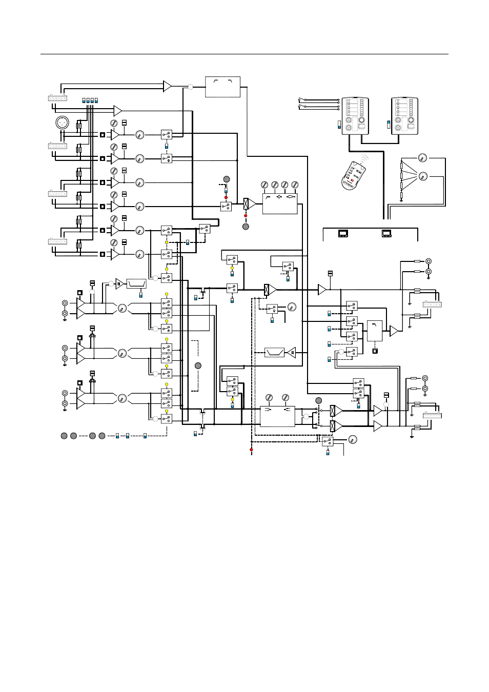
Detailed block diagram
Configuration settings
- The system block diagram shows the many
configuration possibilities to satisfy the unique requirements of each installation.
The DIP switches are labeled with letters for easy identification and logging
using the configuration sheet provided at the rear of this guide.
Mic priority
- When switched, all mics except mic 1 are turned off. Note that
mic 2 becomes the priority mic if mic 1 is configured for paging. In this case,
the paging mic 1 is not affected by the priority switch.
Music priority
- If configured, the pre-level music 1 signal is detected. If it
exceeds a -20dB threshold the Z1 and Z2 FETs are turned off to mute the
currently selected music source. Release time can be set to short or long.
Paging -
Overrides any page enabled zone by ducking the VCA by 20dB
when page signal is detected.
Remote control
- The Zone remote may be custom wired to potentiometers
and switches or connected to the PL-12 wall plate using standard CAT5 cables
as shown here. Other functions may be hard wired to the Utility remote.
SIGNAL DETECT
PAD
TRIM
-
+
MIC1
MIC2
MIC3
MIC4
MIC5
MIC6
LEVEL
PAD
TRIM
-
+
LEVEL
PAD
TRIM
-
+
LEVEL
PAD
TRIM
-
+
LEVEL
PAD
TRIM
-
+
LEVEL
PAD
TRIM
-
+
LEVEL
PK
sig
PAGE
EXPAND
-
+
HPF
MIC EQ
F
HF
-
+
1 2 3456
PHANTOM POWER
PAGE EQ
+4/-10
LEVEL
PK
sig
L
R
MUSIC 1
LF
ZONE 1 EQ
HF
ZONE 2 MIX
MIC MIX
PAGE MIX
L
R
Z1 OUT
1R
1L
A B C D
GR2 AUDIO ZONE MIXER
( R - MUSIC 4 - L )
MIC1
SUB
EQ
LEVEL
L
R
MUSIC 2
LEVEL
L
R
MUSIC 3
Z2 OUT
AUX
AUX
Z2
ZONE 1 MIX
AUX MIX
PK
sig
PK
sig
PK
sig
PK
sig
PK
sig
PK
sig
PK
sig
PK
sig
PK
sig
MONO
FILTER ON
U
PAGE
V
MICS
X
Z2
W
-20dB
G
MIC1 PAGE
VCA
MUSIC 4
MIC MIX
PAGE
PAGE
DUCK
LEVEL
0-10V
O
REMOTE
S
MIC PRIORITY
REMOTE
H
UTILITY REMOTE
PAGE Z1 ENABLE
ZONE 1,2 REMOTE
PAGE Z2 ENABLE
MIC MUTE
MIC PRIORITY
ALARM MUTE
Z1 SOURCE SELECT 0-10V
Z1 LEVEL 0-10V
Z2 SOURCE SELECT 0-10V
Z2 LEVEL 0-10V
REMOTE ALARM INPUT
Z2
PRIORITY
L
T
MF
+
MIX
MIC MUTE
+
I
Z1
+
+
+
Z2
Z1
MUSIC 1
K
MUSIC 1
PRIORITY
+
Z2
Z1
+
Z2
Z1
MUSIC PRIORITY
Z2
MUSIC MIX
F
LOCAL
REMOTE
R
Z1
MIC MIX
LEVEL
0-10V
N
REMOTE LEVEL
E
LOCAL
REMOTE
+
+
+
Z1 OUT
MUSIC MUTE
< Z1 >
< Z2 >
SOURCE SELECT
DUCK
SIGNAL DETECT
MUTE
LEVEL
MUTE
DUCKING
J
LONG RELEASE
M
P
Z1
Z2
REMOTE
Q
MIX ALL (SELECT OFF)
MUTE
+4/-10
+4/-10
SOURCE
FOLLOW
Z1
FOLLOW
Z2
Z1
5
4
3
2
1
PL-5
5
4
3
2
1
6
7
8
9
12
13
10
11
14
PL-12 WALL PLATE
PL-5 IR CONTROLLER
WALL PLATE DISABLE
Z2
Z1
Z2
Z1
WIRING OPTIONS
CAT5
LEVEL
SOURCE
+10V
0V
CUSTOM
REMOTE
WIRED
Z2 FOLLOW Z1
(ROOM COMBINING)