Remote interface connectors, Optional, On air – Allen&Heath XB 14 User Manual
Page 28: Remote a connector wiring, Allen & heath 28 xb-14 user guide, Remote a, Remote b
Allen & Heath 28 XB-14 User Guide
REMOTE INTERFACE CONNECTORS
REMOTE A Connector wiring
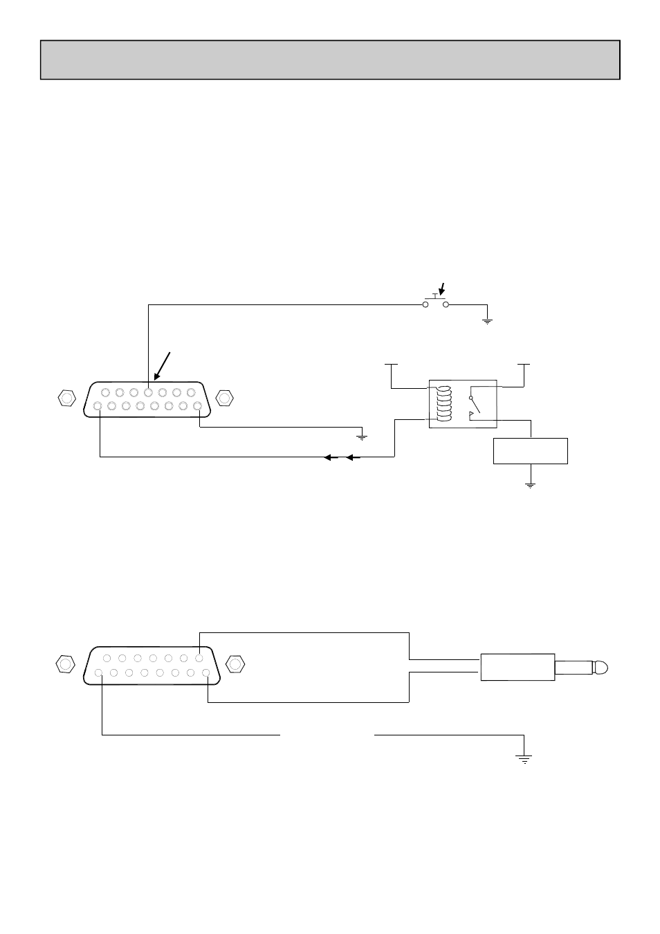
The REMOTE A connector is used for the “Fader Up” logic signals from the Mono and Telco channel faders. It is also
used for remote muting of channels and control room speakers. An example of how these remote signals can be used
is below:
1
2
3
4
5
6
7
8
9
10 11
12
13
14
15
ON AIR
+12V
+12V
REMOTE A
Pin 12 = mute Mono Ch2
Ground
Pin 1 = CH 1 Fader = UP
Input resistor = 10 Ohms for over-current protection.
Ensure input current is less than 100mA
Relay or circuit
Remote mute switch for Mono Ch2
100mA max
1
2
3
4
5
6
7
8
9
10
11
12
13
14
15
Optional
REMOTE B
Start pulse wire to tip
Cue pulse wire to sleeve
3.5mm Jack Plug
Additional Ground wire may be required
To CD player or deck
REMOTE A Connector Example: Remote mute wiring and Fader Up interface
REMOTE B Connector Example: CD Deck start/cue from stereo channel ON switch