2 hardware overview, 1 front panel – AirLive POE-FSH808PW User Manual
Page 11
2. Installation of the Switch
AirLive POE-FSH808PW User’s Manual
6
2.2 Hardware Overview
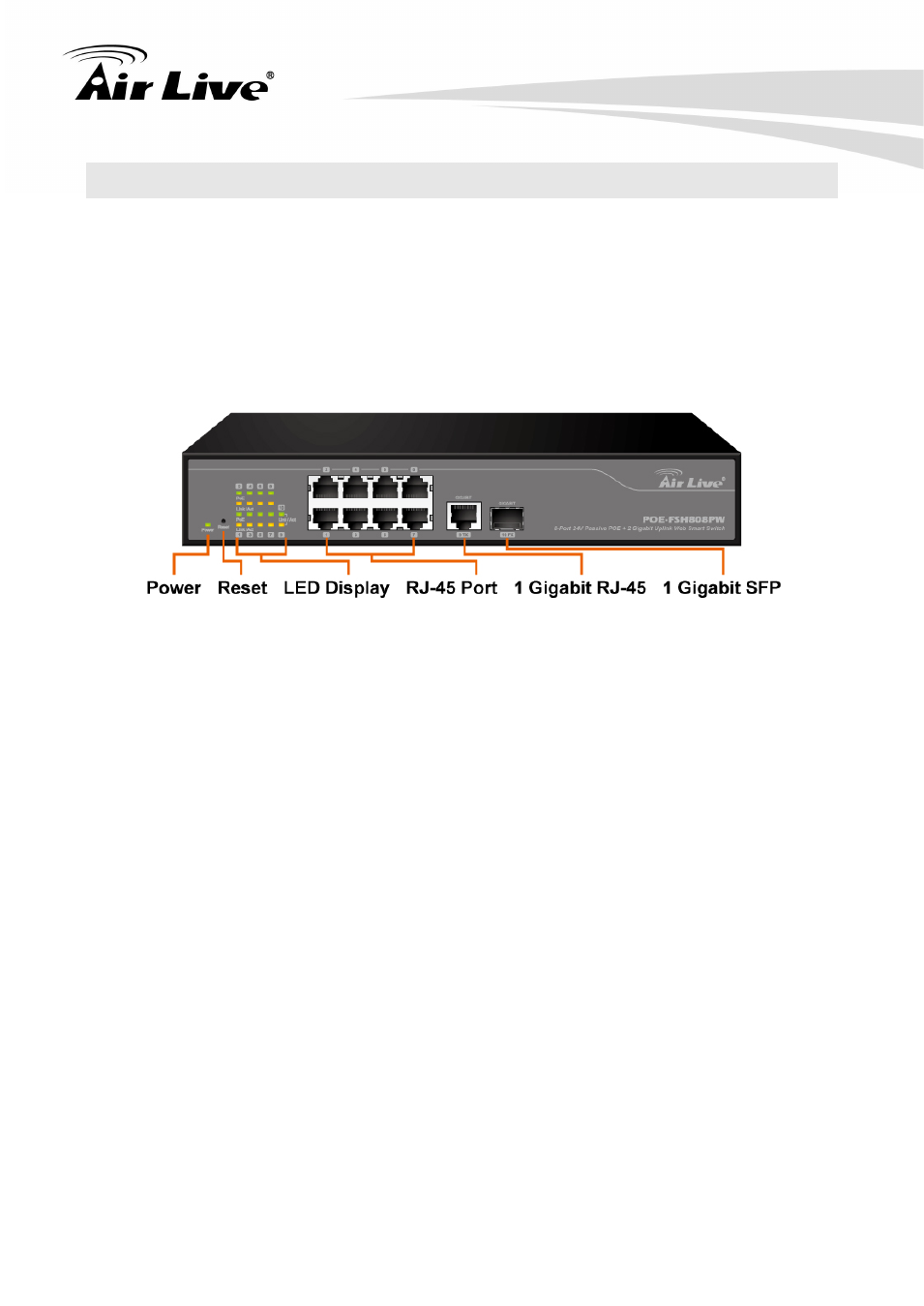
2.2.1 Front Panel
The front panel of the web smart switch consists of 8 10/100Base-TX RJ-45 ports. The LED
Indicators are also located on the front panel.
LED Indicators:
Comprehensive LED indicators display the status of the switch and the network (see the
LED Indicators chapter below).
Front Ethernet Ports:
The front panel of the web smart switch consists of 8 10/100Base-TX RJ-45 ports, 1 Gigabit
RJ-45 and 1 Gigabit SFP uplink ports.
8 10/100Base-TX RJ-45 ports are PoE enable ports. These PoE ports will be automatically
activated when a compatible terminal is identified, and the PoE port will supply power to the
connected PoE device.
For legacy devices that are not yet compatible, the PoE port will not offer the power to
these devices. This feature allows users to freely and safely mix legacy and Power over
Ethernet compatible devices on their network.
These ports support network speeds of either 10Mbps or 100Mbps, and can operate in half-
and full- duplex transfer modes. These ports also support the automatic MDI/MDIX
crossover detection function, providing true “
plug and play” capability. Just plug-in the
network cable to the hub directly and regardless if the end node is a NIC (Network Interface
Card) or switch and hub.