ACU-RITE ENC 125 T/E User Manual
Page 6
Acu-Rite Companies Inc.
4
Mounting Information
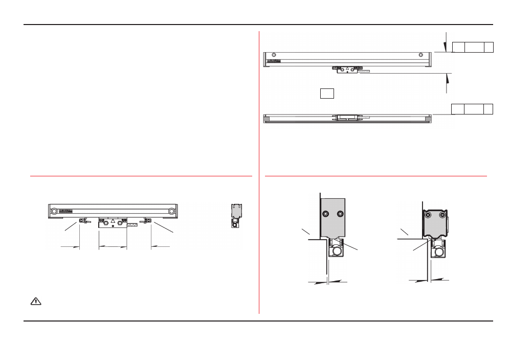
ENC 125 T/E
Use this information to plan your Linear Encoder
installation.
• Mount the linear encoders close to machine guide ways to
ensure system accuracy.
• If space between the reading head and the mounting
surface exceeds .18”, use a mounting bracket or spacer to
reduce space.
• Acu-Rite Companies Inc. bracket kit instructions provide
step by step installation procedures.
• Tolerances of .010” TIR apply to all mounting dimensions.
• Top mounted form X= 2.37”.
• End mounted form X= 1.90”.
• Clearance requirements for alignment bracket removal.
• Alignment brackets must not be removed until
instructed.
• Use reading head leveling set screws.
• Reading head bracket required for a space >.18”.
Offset
mounting
Move bracket past
the cable strain relief
Alignment bracket removal clearance
1.0
[25mm]
1.38
[35mm]
Alignment
bracket
Alignment
bracket
(ENC 125 E end mounting scale case shown for reference)
ENC 125 T
ENC 125 E
.005 - .180”
Max. Gap
.005 - .180”
Max. Gap
Underside of end
caps to be flush
with the parting
line
Axis parting
line
Axis parting
line
// .010 A
// .010 A
X
-A- = Axis travel
Tolerances ...