ACU-RITE ENC 125 T/E User Manual
Page 11
These steps apply to typical encoder mounting conditions and
assumes the mounting surface is parallel to the machine
travel to within .010”.
• Acu-Rite Companies Inc. bracket kit instructions supercede
this section.
• Adjust drill depths and fastener lengths as required.
• Contact your authorized Distributor should you require
additional assistance.
• Move the reading head to the center of the scale case by
sliding the reading head and brackets along the case.
• Move the machine axis to its center of travel and mark the
axis for future reference.
• Locate the encoder so that a suitable mounting position is
provided for both the scale case and the reading head.
Keep the underside of end caps approximately flush with
the underside of the table (or axis parting line).
• Mark the location of one end mounting hole to the
mounting surface and remove encoder.
9
Acu-Rite Companies Inc.
ENC 125 T/E
Encoder Installation Procedure
Scale case
Reading head assembly
Alignment brackets (2)
CL
Center mounting axis
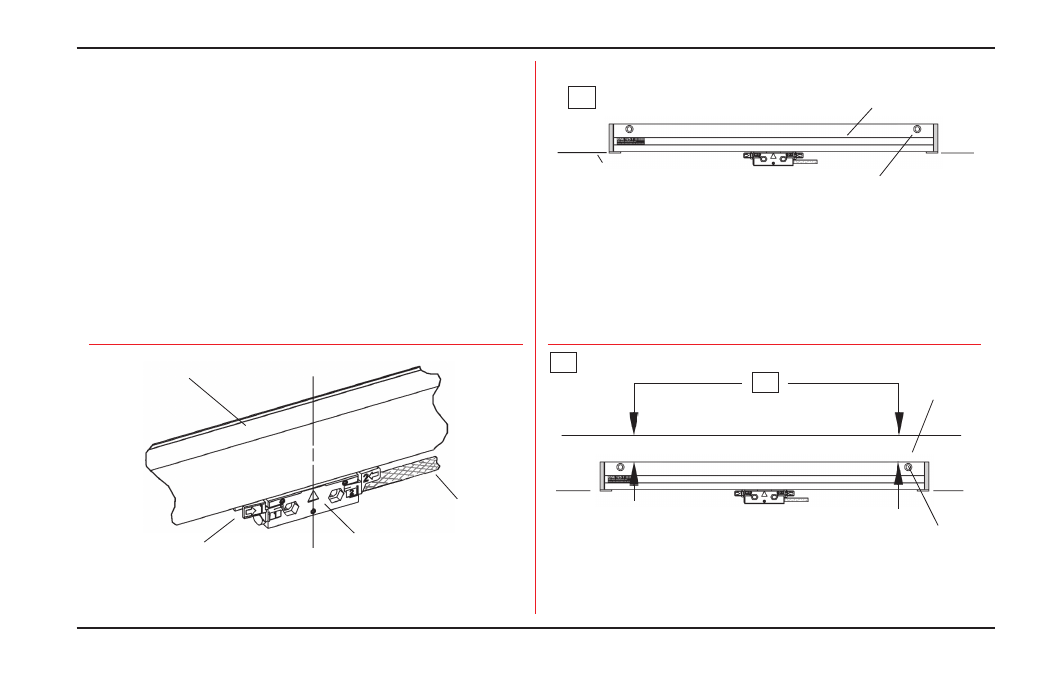
Align top of scale case to
within .015” of -A-
Cable assembly
Scale case
Axis parting line
End mounting hole (typical)
• Drill & tap the first end mounting hole location.
• Attach the encoder and align to within .010” TIR. to -A-.
• Transfer punch the remaining mounting holes and remove
the encoder.
10-32 x1-1/4” SHCS & M5 flat washer
Align to within .010” TIR to -A-
-A-
Drill / tap
for 10-32
-A- = Axis travel
-A- = Axis travel