ACU-RITE ENC 125 T/E User Manual
Page 12
Acu-Rite Companies Inc.
10
Encoder Installation Procedure
ENC 125 T/E
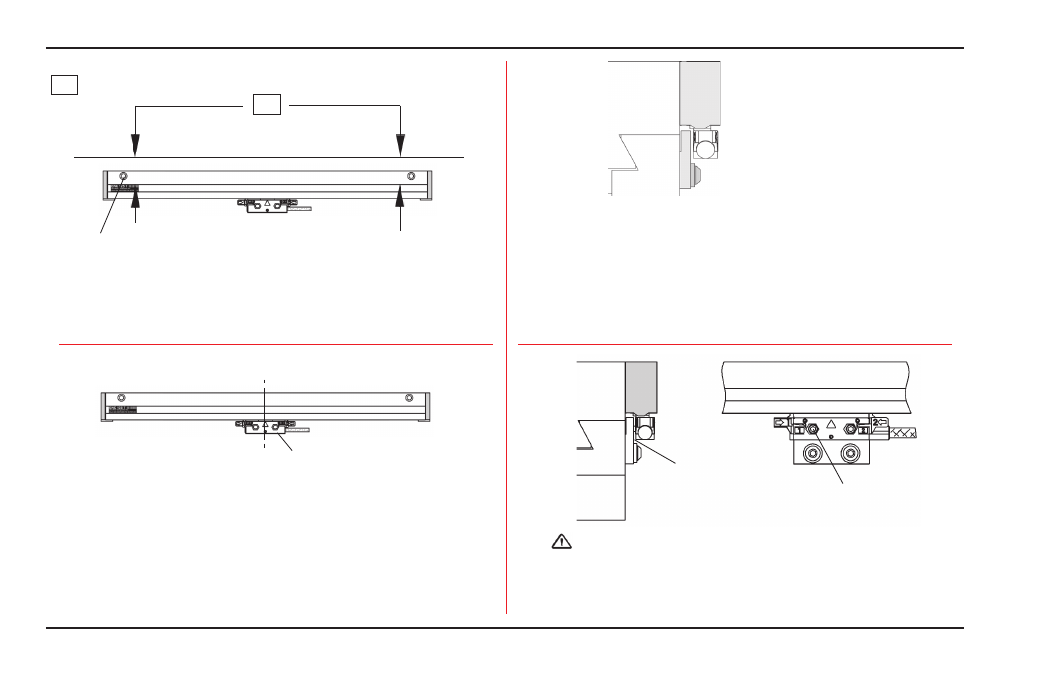
• Return the table to the center of travel. Move the reading
head to the center of the scale case.
• Transfer punch the two reading head mounting holes. If
using a reading head bracket, use the next step.
• Slide the reading head to one side, and drill and tap the
hole locations for an 8-32 x 1/2” deep.
• Attach the bracket to the reading head with the 8-32 x 5/8”
BHCS.
• Transfer punch the two reading head bracket mounting
holes to the machine.
• Remove the bracket, drill and tap the hole locations for an
1/4-20 x 1/2” deep. Attach the bracket to the machine with
(2) 1/4-20 x .5” BHCS and washers.
10-32 x 1-1/4” SHCS & M5 flat washer
Align to within .010” TIR to -A-
-A-
• Drill / tap the remaining mounting holes.
• Attach the encoder and align the face and the top of the scale case
to within .010” TIR. to -A- (refer to page 4, “Tolerances”).
• Secure the encoder in place maintaining this alignment.
CL
Reading head mounting holes
Reading head bracket
8-32 x 5/8” SHCS
(M4 x 20mm)
•
Insert, but do not tighten 8-32 (M4) reading head screws.
•
A gap will exist between the reading head and the
bracket.
Gap
Do not tighten prior to adjusting leveling set screws
-A- = Axis travel