Echo 72928 Owners Manual v.4 User Manual
Page 9
6
Detent
Ball
Clevis
Assembly
Nut
Insert cable
through hole
Feed
Control
Lever
Cable
Anchor
Weldment
Hydrostat
Control
Cable
S
E C T I O N
2
weldment as shown in figure 2.1. Use a 3/8" x
2-1/2" bolt, washers, and nut to attach the two
safety chains with hooks as shown.
4. Push the top link pin through the holes in the hitch
and trailer. Secure the top link pin with a lynch pin.
Adjust the hitch to make the chipper trailer as level as
possible when connected to the towing vehicle.
2.1.3 Attach the Chute Support
Attach the chute support to the trailer using one 3/8" x
1-1/4" bolt, washer, and locknut. Refer to figure 2.1.
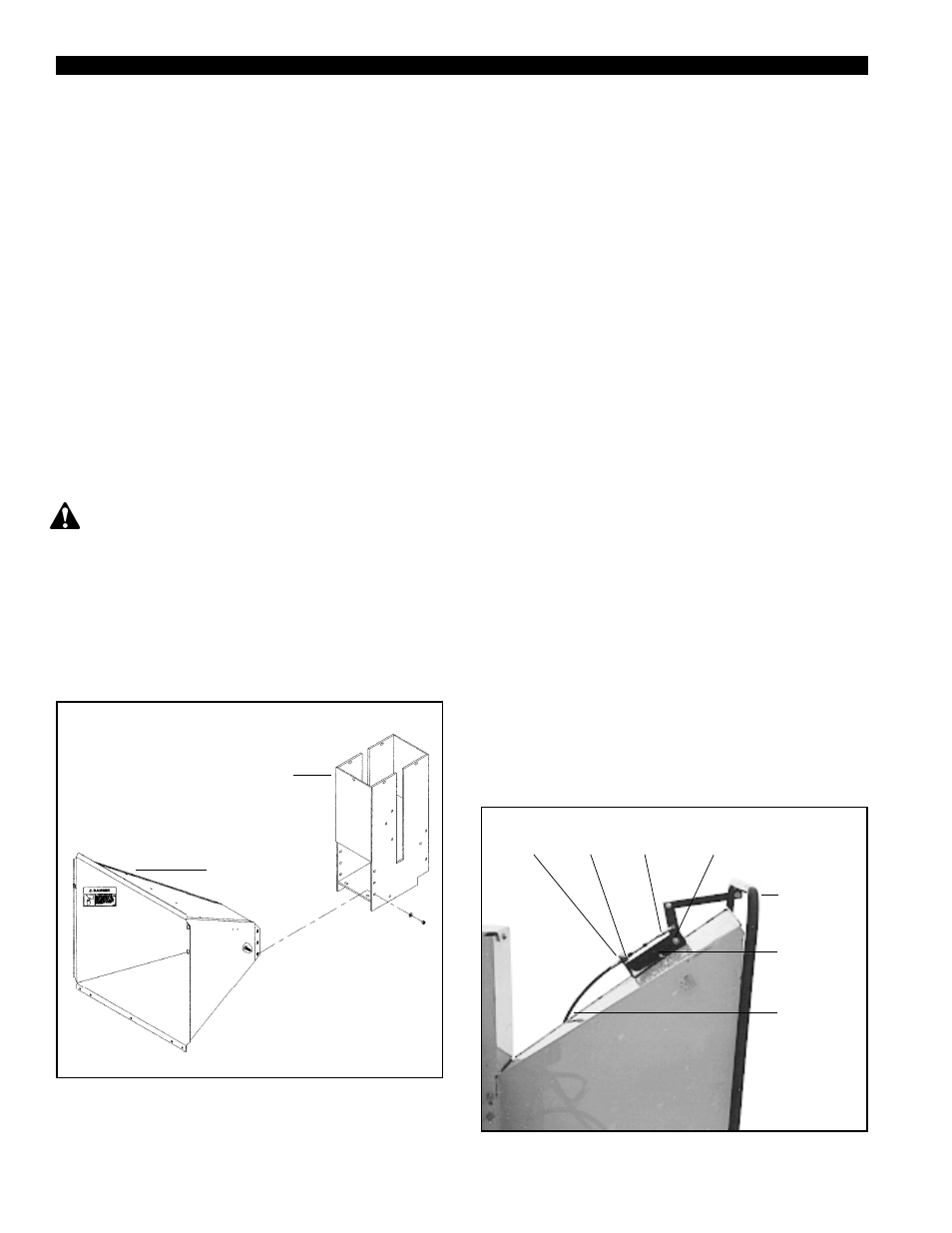
2.1.4 Attach the Chipper Chute
Do not operate this unit without the chipper chute
correctly installed. Rotating cutting blades can cause
serious personal injury.
Mount the chipper chute to the hydraulic feed using
eight 3/8" x 1" bolts and locknuts. To insert the top
bolts, you may need to temporarily lift the grab roller
with a pry bar. Use three bolts on each side and two on
the bottom (see figure 2.2).
2.1.5 Attach the Chute Extension Tray
1. After mounting the chute to the hydraulic feed, slide
Hydraulic
Feed
Chipper
Chute
Figure 2.2
Figure 2.3
the chute extension tray over the chipper chute as
shown in figure 2.1. Make sure that you posi-
tion the lip on the extension tray behind the
lip on the chipper chute. Align the five bolt holes
in the chute extension tray with the bolt holes in the
extension hinge.
2. Insert a 3/8" x 1" carriage bolt (included in owners
kit packaged with the chipper) through the two
outside holes on the extension tray and the exten-
sion hinge. Secure the bolts with washers and
nuts.
3. Insert one 3/8" x 1" carriage bolt through the end of
the chute support and middle holes on the exten-
sion hinge and extension tray. Secure the bolts
with washer and nuts. Secure with hairpin clips.
2.1.6 Connect the Control Cable
1. Remove the clevis assembly from the hydrostatic
control cable end (see figure 2.3). Remove one
nut on the cable end. Insert the cable end into the
hole in the cable anchor weldment. Replace the
nut and the clevis assembly.
2. Attach the clevis assembly to the center hole on
the feed control lever.
3. Adjust the cable detent ball to hold the control arm
is in the forward position or neutral position
detents.
2.1.9 Before Using