7 raising the feed roller, 6 setting blade clearance, 5 installing the blades – Echo CH500H Owners Manual v.1 User Manual
Page 17: Warning
5" and 8" Skid Steer Chipper
13
SERVICE & MAINTENANCE
BeFOre iNSPeCtiNg Or ServiCiNg aNy Part OF tHiS MaCHiNe, SHut OFF POWer SOurCe,
diSeNgage tHe HydrauliCS aNd Make Sure all MOviNg PartS Have COMe tO a COMPlete StOP.
Warning
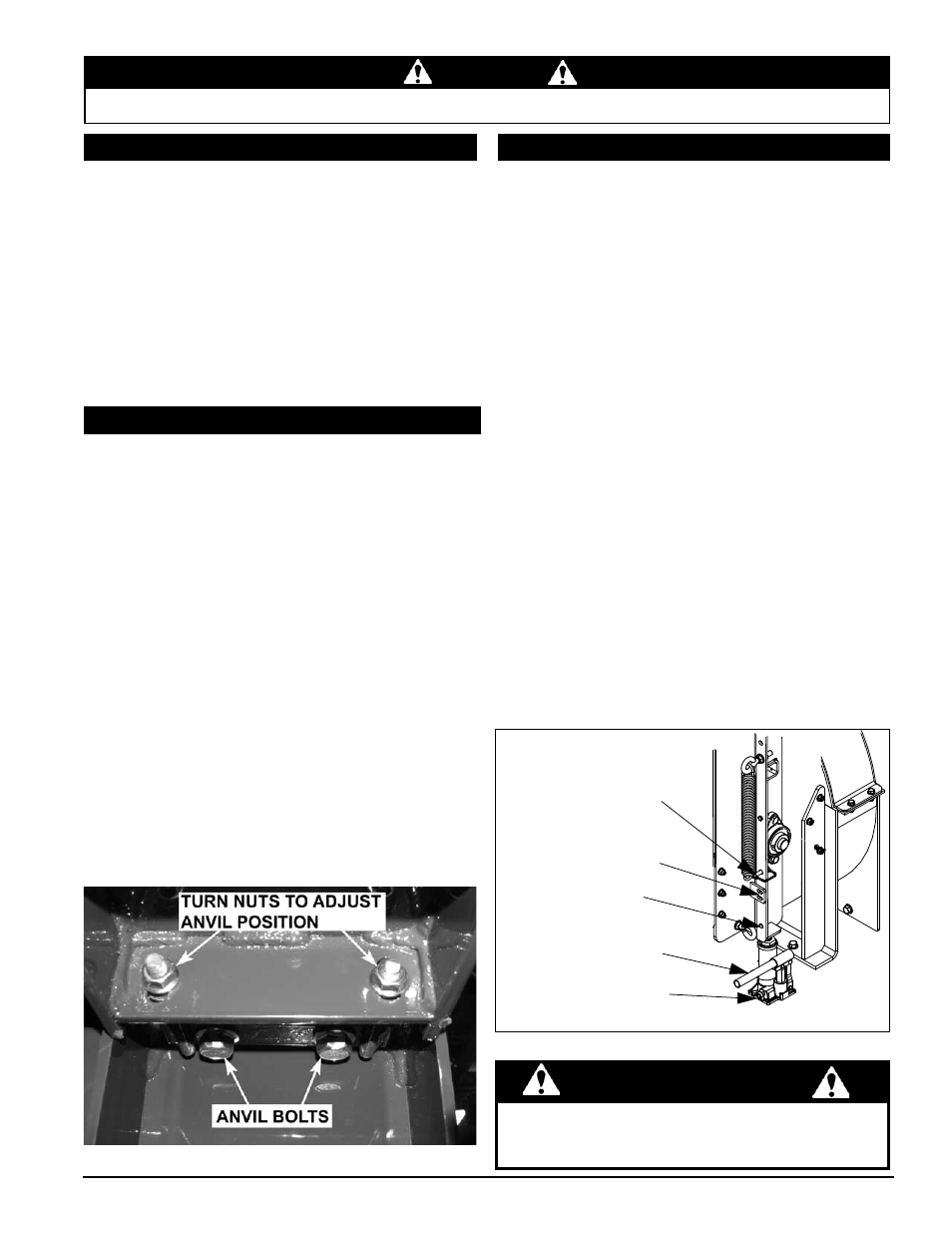
the chipping blades should clear the anvil by 1/16 to 1/8
inch. To adjust the blade clearance, proceed as follows:
loosen the two (CH500H) or three (CH800H) anvil
1.
bolts located underneath the feed roller housing (see
Figure 5.2).
Open the chipper blade access cover to view the gap
2.
between the blades and anvil
On the CH500H, move the anvil assembly in or out
3.
by turning the nuts on the block adjuster weldment.
On the CH800H, with the three anvil bolts loosened,
adjust the anvil to the desired position.
it is important to ensure that the minimum gap between
4.
the chipping anvil and all chipping blades is 1/16".
all chipping blades should be rotated until even with
the chipping anvil and then measured. Failure to
do so can result in the chipping blades striking the
chipping anvil causing serious injury or death.
if the anvil cannot be moved to specifications due to
5.
wear, rotate the anvil or replace the anvil.
Secure all hardware and adjust to torque.
6.
Figure 5.2 - Adjusting blade clearance (CH500H shown here)
remove any accumulated material from the blade
1.
pocket and the bottom of the chipper blade.
reinstall the chipper blades and tighten the bolts
2.
to a torque of 25 Ft-lbs. (CH500H) or 120 Ft-lbs.
(CH800H).
Check the blade/anvil clearance and adjust if necessary.
3.
Close the chipper housing and secure with removed
4.
bolts to a torque of 25-28 Ft-lbs.
reconnect machine hydraulics.
5.
5.5 insTalling The blades
5.6 seTTing blade clearance
5.7 raising The feed roller
The feed roller lift jack is used to raise the feed roller to service
the machine or to clear material that has gotten wedged in
or behind the feed roller. to raise the feed roller:
Stop skid steer engine, disengage hydraulics, and allow
1.
the machine to come to a complete stop.
Position the chipper chute to the side of the chipper.
2.
remove the two bolts on the chipper blade access
3.
cover.
tip the cover away from the chipper to expose the rotor
4.
and the blades.
Turn the check valve located on the bottom of the jack
5.
clockwise, engaging the jack.
remove the lock pin from its storage position (see
6.
figure below).
Pump the handle to raise the feed roller until the lock pin
7.
position aligns with one of the support bracket holes.
Secure the position by putting the lock pin through the
8.
support bracket and lock pin position. this will ensure
the feed roller cannot fall from the upright position.
Service the machine.
9.
to lower the feed roller support, remove the lock
10.
pin and then turn check valve counterclockwise to
disengage the pump.
replace lock pin in storage position.
11.
lower access cover and reattach the two bolts.
12.
Figure 5.3 - Feed Roller Lock
CHECK
VALVE
LOCK PIN
POSITION
FEED ROLLER
JACK
SUPPORT
BRACKET
LOCK PIN IN
STORAGE
POSITION
the feed roller must be secured in the up position prior
to servicing the chipper feed area. Failure to do so can
result in serious injury or death.
Warning