Echo CH8670H Instruction v.5 User Manual
Page 6
Instruction Sheet
6
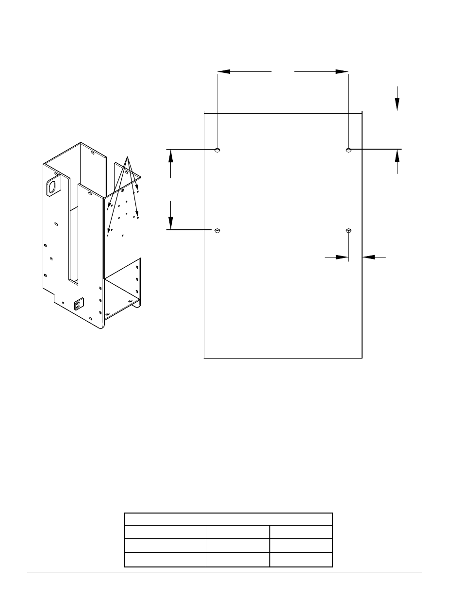
Drill four holes 9/32" in diameter in the chipper feed tower to accomodate the new controller. Drill them on the same
9.
face of the feed tower that the Smart Relay was located. See diagram below for correct placement of holes.
.815"
6.0"
8.0"
2.75"
NEW
HOLES
Bolt the Plus 1 controller enclosure onto the chipper in the holes just drilled with four (4) 1-1/4 x 3/4" bolts, washers
10.
and nuts. Thread the bolts through from inside the machine.
OPERATION
Upon initial startup, make sure the chipper is in Neutral position.
1.
Observe the LED light while starting the chipper engine. If the chipper feed control is in any position other than
2.
Neutral, the LED will flash red and forward feed will not be available.
Upon initial startup, if the chipper is in Neutral position, the LED will flash green, indicating that the RPM is not high
3.
enough to chip (see the Optimal Rotor and Engine RPM chart).
Increase RPM gradually until the LED is solid green. Forward feed is now available.
4.
See the Control Light Flash codes table on the following page for a complete explaination of all flash codes provided
5.
by the LED.
OPTIMAL ROTOR AND ENGINE RPM
OPTIMAL ROTOR AND ENGINE RPM
Chipper Model
Rotor RPM
Engine RPM
CH8993H (76835)
1500
3750
CH8670H (76824)
1500
3750