Domestic (usa, canada, and south america) wiring – Echo CH8670H Instruction v.5 User Manual
Page 4
Instruction Sheet
4
Next, unclamp the wires from the Smart Relay controller and connect them to the Plus 1 controller harness from the
6.
kit. These wires can be connected to the controller harness in two ways:
Either solder the wires on the controller harness to the wires on the chipper harness or,
A.
Use the female and male connectors supplied with the kit.
B.
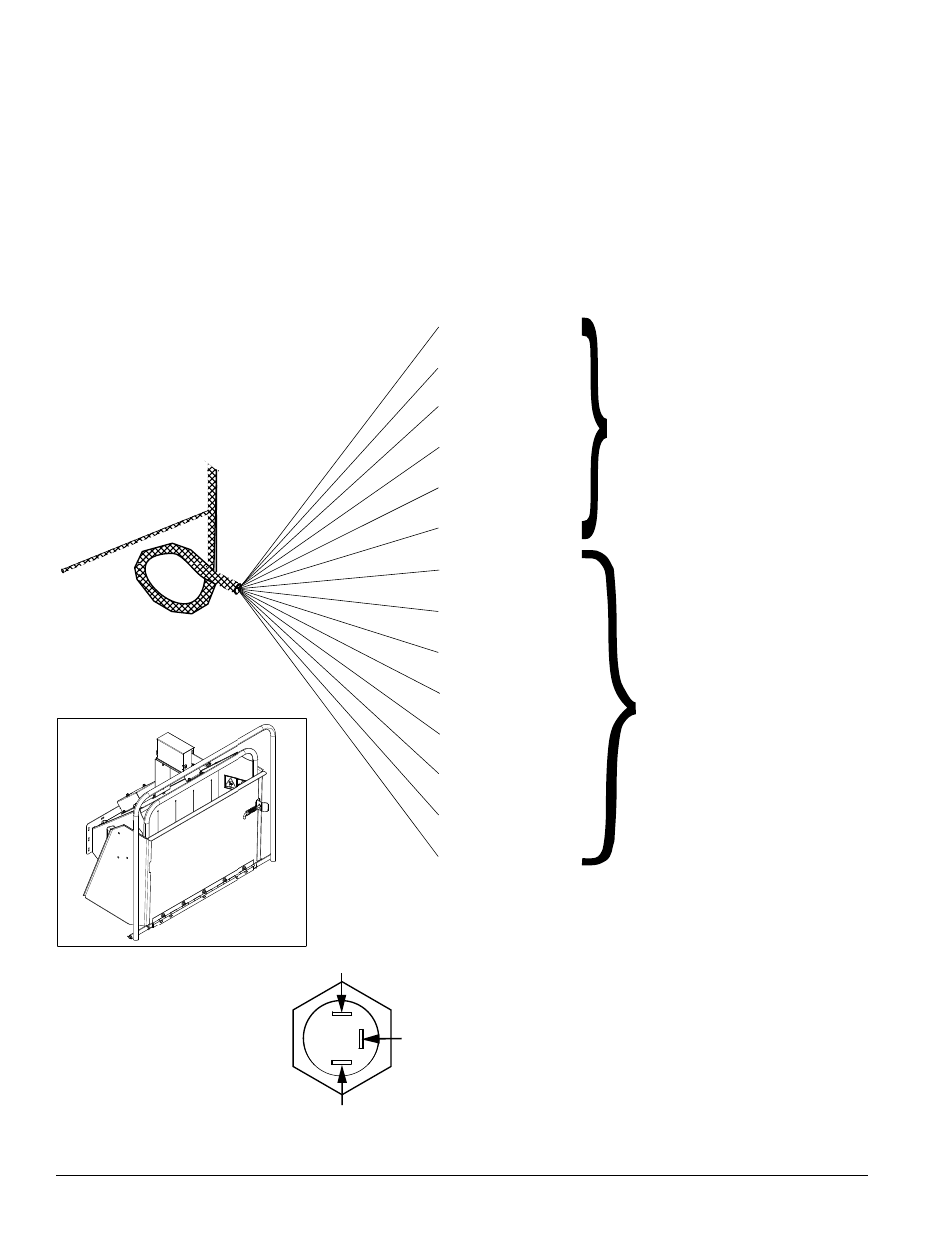
Some of the wires coming from the Plus 1 controller harness will not be used. Three of them will connect to the LED.
The rest will connect to the chipper harness. Use one of the diagrams below to connect the wires correctly. NOTE:
Each wire has a number marked on it. Use these numbers to distinguish between the three different red wires.
GREEN/BLACK
ORANGE/BLACK
RED (#1 WIRE)
WHITE
GREEN
ORANGE
BLACK
YELLOW
LIGHT GREEN
RED/BLACK
RED/YELLOW
RED (#3 WIRE)
RED (#2 WIRE)
DO NOT CONNECT TO PLUS 1
HARNESS. TAPE EACH END
INDIVIDUALLY AND THEN
TAPE ALL SIX WIRES
TOGETHER.
CONNECT TO WIRES OF
MATCHING COLOR ON
THE PLUS 1 HARNESS.
CONNECT WIRES FROM THE PLUS 1
HARNESS TO THE TRI-COLORED LED
AS SHOWN HERE.
CHIPPER
HARNESS PN
18547-00
RED (#4 WIRE)
RED/YELLOW
WHITE
BLUE
DOMESTIC (USA, CANADA, AND SOUTH AMERICA) WIRING
WITHOUT KNEEBAR