JLG LSS Verticals Operator Manual User Manual
Page 15
SECTION 2 - SERVICE PROCEDURES - LOAD SENSING SYSTEM
3124289
– JLG Lift –
2-7
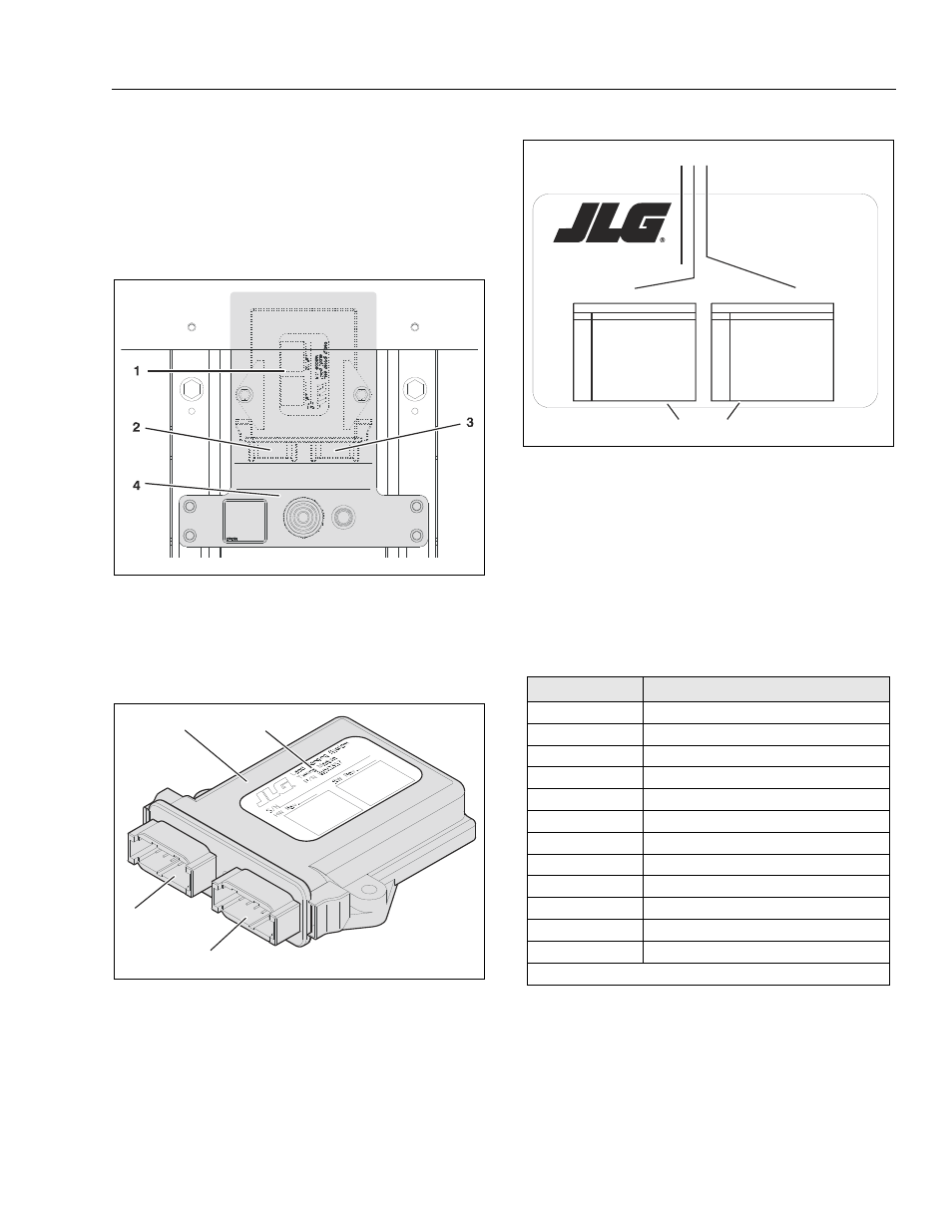
2.4 LSS TIMING MODULE -
(MANUALLY PROPELLED LIFTS ONLY)
The LSS Timing Module is fastened to the back of the LSS
Indicator Panel at the back of the platform on the mast
header. (See Section 2.3, Component Removal for instruc-
tions on removing the module).
LSS Module Location
1. Timing Module
3. J2 Grey Connector
2. J1 Black Connector 4. LSS Indicator Panel
LSS Timing Module
1. Timing Module
3. J2 Grey Connector (unused)
2. Identification Decal 4. J1 Black Connector (used)
1
2
3
4
LSS Timing Module Identification Decal
with Connector Pin Assignments
1. Module Serial Number
2. Hardware Revision Level
3. Software Revision Level
4. J1 Black - Pin Assignments (used)
5. J2 Grey - Pin Assignments (unused)
Table 2-2. LSS Timing Module
(J1 - Black Connector)
Pin Assignments
Pin
Signal
Description
1
12V +
Ignition
2
Neg. (—)
Ground
3
12V +
Overload Limit Switch Input
4
–
Spare Input 1
5
–
Spare Input 2
6
–
Spare Input 3
7
12V +
Overload Status Output
8
12V +
Visual Warning Output
9
12V +
Audible Warning Output
10
–
Spare Input 4
11
–
Spare Input 5
12
–
Spare Input 6
Note: Also refer to wiring diagram Figure 2-5.
Load Sensing System
Timing Module
P/N 1600357
S/N_________________________________
HW Rev.________
SW Rev.________
1
2
3
4
5
6
7
8
9
10
11
12
1
2
3
4
5
6
7
8
9
10
11
12
IGNITION
GROUND
Overload Limit Switch input
Spare Input 1
Spare Input 2
Spare Input 3
Overload Status Output
Visual Warning Output
Audible Warning Output
Spare Output 3
Spare Output 4
Spare Output 5
+5 Analog Reference
Spare Analog 0
Analog Ground
+5 Analog Reference
Spare Analog 1
Analog Ground
Spare Analog 2
Spare Analog 3
CANBus CANH
CANBus CANL
Analyzer Pin #3
Analyzer Pin #2
PIN FUNCTION
PIN FUNCTION
J1 - BLACK
J2 - GREY
170
576
0A
1 2 3
4
5