JLG 45e Service Manual User Manual
Page 38
SECTION -
-12
– JLG Lift –
3120861
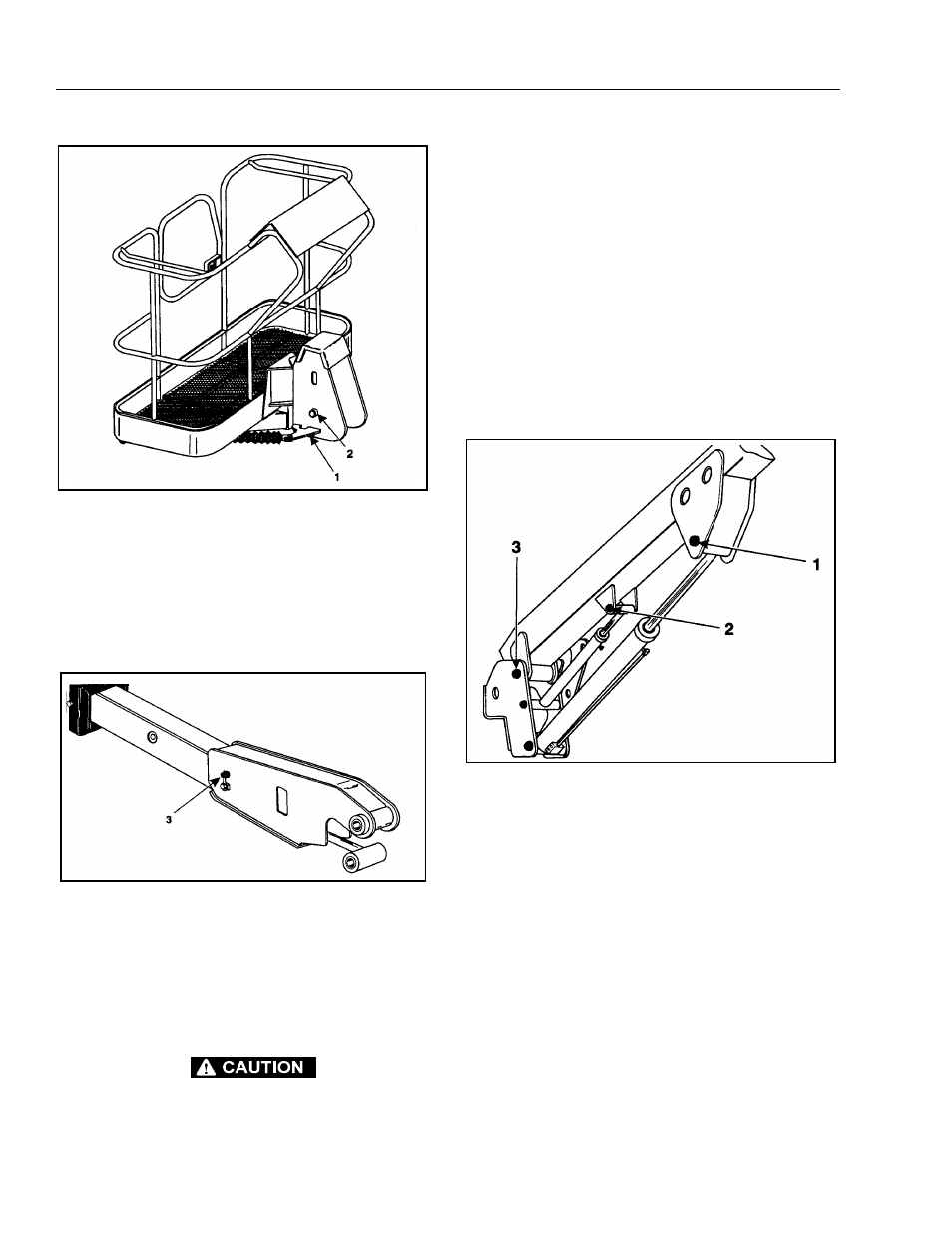
e. Supporting the slave cylinder, remove the hard-
ware from pin #3. Using a suitable brass drift
and hammer, remove pin #3 from the fly boom.
f.
Tag and disconnect hydraulic lines to the slave
leveling cylinder. Use a suitable container to
retain any residual hydraulic fluid. Cap hydraulic
lines and ports. Remove the slave cylinder.
2.
Remove the boom from upright as follows:
a. Remove hardware securing the cover plate on
the side of the base boom section and remove
hose clamps. Disconnect wiring harness from
ground control harness connector.
HYDRAULIC LINES AND PORTS SHOULD BE CAPPED IMMEDI-
ATELY AFTER DISCONNECTING LINES TO AVOID ENTRY OF
CONTAMINANTS INTO SYSTEM.
b. Tag and disconnect hydraulic lines from boom
to control valve. Use a suitable container to
retain any residual hydraulic fluid. Cap hydraulic
lines and ports.
c. Using a suitable lifting equipment, adequately
support boom weight along entire length.
d. Remove hardware securing the lift cylinder pin
#1. Using a suitable brass drift and hammer,
remove pin #1 from the base boom.
e. Remove hardware securing the master cylinder
pin #2. Using a suitable brass drift and hammer,
remove pin #2 from the base boom.
f.
Remove hardware securing the base boom pin
#3. Using a suitable brass drift and hammer,
remove pin #3 from the upright.
g. Using all applicable safety precautions, carefully
lift boom assembly clear of upright and lower to
ground or suitable supported work surface.
Figure 2-5. Location of Components -
Platform Support. (Models 35/n35/40/n40/45)
Figure 2-6. Location of Components - Slave Leveling
Cylinder.
Figure 2-7. Location of Components - Removal of Base
Boom. (Models 35/n35/40/n40/45)