5 rear locking caster wheel - operation, 6 platform controls - operation, Before elevating platform – JLG 9MP Operator Manual User Manual
Page 23: Platform emergency stop/shut-down button, Rear locking caster wheel - operation -5, Platform controls - operation -5, Rear caster wheel (locking) -5
SECTION 3 - MACHINE CONTROLS, INDICATORS AND OPERATION
3121162
– JLG Lift –
3-5
3.5
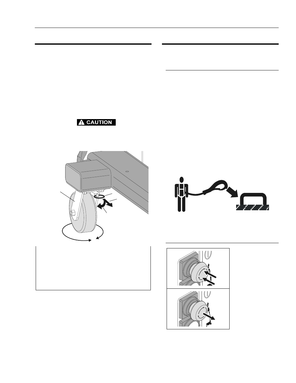
REAR LOCKING CASTER WHEEL -
OPERATION
Machines equipped with rear caster wheels and front
caster wheels allow for high machine maneuverability in
close quarters. The right rear (gate side) caster wheel can
be locked at 90° increments in it’s 360° of rotation. This
caster must be locked parallel with the base frame when
setting the floor stop and elevating the platform to limit
machine movement, or when pushing the machine uphill,
allowing the operator more control of the machine. See
illustration below for locking and unlocking instructions of
the rear caster wheel.
WHEN PUSHING MACHINE UP A GRADE, OR ELEVATING THE
PLATFORM, LOCK THE RIGHT (GATE SIDE) REAR SWIVEL
CASTER WHEEL PARALLEL WITH THE BASE FRAME.
3.6
PLATFORM CONTROLS - OPERATION
(See Figure 3-3.)
Before Elevating Platform
• Check the BUBBLE LEVEL INDICATOR on the base
frame, that machine is resting on a level (firm and uni-
form) surface.
• Turn the MAIN POWER SWITCH (Key) to ON at the
ground control station.
• Check that EMERGENCY STOP BUTTON at the
ground control station is in the RESET position.
• SET the floor stop mounted on the right side of the
machine under the base frame.
• If machine is equipped with rear wheel casters, lock
the right rear (gate side) caster wheel parallel with the
base frame before attempting to raise the platform. See
Figure 3-2.
• Attach fall protection lanyard to attach bar on platform
railing. Maximum lanyard length is 30 in. (76cm). See
Figure 3-3. for location of attach bar.
• Check that EMERGENCY STOP BUTTON at the plat-
form control station is in the RESET position.
Platform Emergency Stop/Shut-Down Button
1. 360° Swivel Locking Caster 3. Pull out to release wheel
2. Caster Wheel Locking Pin
4. Turn the ring 90° to lock the
pin in the out position allowing
the wheel 360° swivel rotation.
Note: The right rear (gate side) caster wheel can be locked at
every 90° of swivel rotation. Wheel is shown locked parallel with
base frame in picture above.
Figure 3-2. Rear Caster Wheel (Locking).
1
2
3
4
POWER OFF
PUSH IN -
TO ENGAGE
Emergency Stop.
POWER ON
TURN CLOCKWISE
and RELEASE -
TO RESET
Emergency Stop.