1 general, 2 machine description, 3 machine operation – JLG 9MP Operator Manual User Manual
Page 20: Getting started, 4 ground controls - operation, Main power selector switch (key), Emergency stop/shut down button, Battery discharge indicator (bdi), General -2, Machine description -2
SECTION 3 - MACHINE CONTROLS, INDICATORS AND OPERATION
3-2
– JLG Lift –
3121162
3.1
GENERAL
IMPORTANT
TH E M A N U FA C TU R E R H A S N O D I R E C T C O N T R OL OV E R
MACHINE APPLICATION AND OPERATION. THE USER AND
OPERATOR ARE RESPONSIBLE FOR CONFORMING WITH GOOD
SAFETY PRACTICES.
This section provides the necessary information needed
to understand control function and operation.
3.2
MACHINE DESCRIPTION
The 9MP Model Lift is a manually propelled vertical lift with
a platform/material tray mounted to an elevating alumi-
num mast mechanism. The personnel lift’s intended pur-
pose is to provide personnel access to areas above
ground level.
The platform is raised and lowered by controls located in
the platform.
A ground control station is provided to be used during
machine power-up, or in case of emergency should the
operator in the platform be unable to lower the platform.
Vibrations emitted by these machines are not hazardous
to an operator working in the platform.
The continous A-Weighted sound pressure level at the
work platform is less than 70db (A).
3.3
MACHINE OPERATION
Getting Started
The following control conditions must be met before the
platform can be elevated.
• The battery contains enough voltage to operate the
machine, check the battery discharge indicator
mounted on the battery charger.
• The machine must be positioned on a firm, level work
surface (check the bubble level indicator mounted on
the right front corner of the base frame).
• The main power selector switch (key) must be set to
the ON position.
• Both emergency stop buttons, one on the ground con-
trol station, the other on the platform control station
must be in the reset (out) position.
• The floor stop must be set to keep the machine free
from movement when the platform is elevated.
• If machine is equipped with rear wheel casters, lock
the right rear (gate side) caster wheel parallel with the
base frame before attempting to raise the platform. See
Figure 3-2.
3.4
GROUND CONTROLS - OPERATION
(See Figure 3-1.)
NOTE: If equipped with optional Programmable Security
Lock (PSL) see Section 3.8 for additional instruc-
tions.
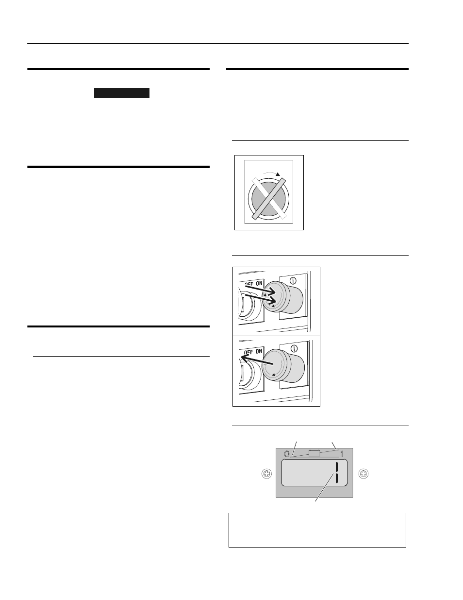
Main Power Selector Switch (Key)
Emergency Stop/Shut Down Button
Battery Discharge Indicator (BDI)
Set the main power switch (key)
to ON to power up the machine or
OFF to power the machine down.
To prevent unauthorized use
remove key.
POWER OFF
PUSH IN to engage or
power down.
POWER ON
TURN CLOCKWISE
and RELEASE to
RESET or power on.
Battery Discharge Indicator
1. Low Battery Voltage
3. Charge Indicator LED
2. High Battery Voltage
OFF ON
R
E
SET
R
E
SET
+
-
1
2
3