Drives in opposite direction, Overview of procedure, Check for these obvious conditions first – JLG 15VPSP Service Manual User Manual
Page 75: Table 3-15. drives in opposite direction, Drives in opposite direction -21
SECTION 3 - TROUBLESHOOTING
3120728
– JLG Lift –
3-21
Drives In Opposite Direction
Overview Of Procedure
The following procedure checks that both the drive motor power wire connections correctly installed and are secure and
tight. Also that the joystick control assembly for proper installation at the platform control box.
Check For These Obvious Conditions First:
• If the Left Drive Motor (X103) connector is switched with the Right Drive Motor (X104) connector at the MC-1 box, you will
immediately get an 2 LED flashing Error Code at the Platform Control when the machine is powered up.
• Check Joystick Calibration (See Procedure in Service Manual, Section-2).
* Note: If the Orange, 55-3 or 55-6 wires to the right drive motor in the X104 connector or the Orange, 55-7 or 55-10 wires to
the left drive motor in the X103 connector at the MC-1 controller are crossed up that drive motor will run backwards.
** Note: If platform controller is not under warranty, the internal components of the platform controller are replaceable and
can be ordered and replaced seperately from the complete platform control box. See procedures in Section-2 of
this Service Manual for Joystick Assembly/ Disassembly.
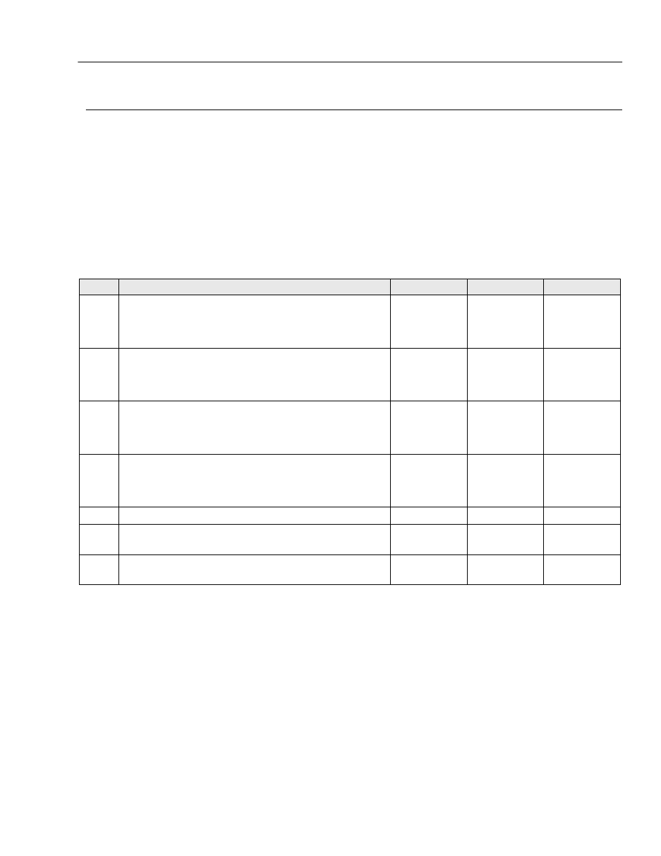
Table 3-15. Drives In Opposite Direction
STEP
ACTION
SPEC
YES
NO
1.
Check the connection of the Orange, 55-3 wire to the right drive
motor at both ends;
• At the X104 connector on the MC-1 box, pin A1.
• And the Black wire at the Drive Motor end.
—
Go to Step 2
* Repair or
Replace
Connection
2.
Check the connection of the Orange, 55-6 wire to the right drive
motor at both ends;
• At the X104 connector on the MC-1 box, pin A2.
• And the White wire at the Drive Motor end.
—
Go to Step 3
* Repair or
Replace
Connection
3.
Check the connection of the Orange, 55-7 wire to the left drive motor
at both ends;
• At the X103 connector on the MC-1 box, pin A1.
• And the Black wire at the Drive Motor end.
—
Go to Step 4
* Repair or
Replace
Connection
4.
Check the connection of the Orange, 55-10 wire to the left drive
motor at both ends;
• At the X103 connector on the MC-1 box, pin A2.
• And the White wire at the Drive Motor end.
—
Go to Step 5
* Repair or
Replace
Connection
5.
Is platform control box under warranty? **
—
Order New One
Go to Step 6
6.
Internal to the platform control - check that the joystick assembly
inside the platform control has not been installed backwards.
—
Re-install
Correctly
Go to Step 7
7.
Internal to the platform control - check that the joystick assembly
wiring to the platform control circuit card is not wired backwards.
—
Re-install
Correctly
Consult Factory