Emergency stop switch removal – JLG 15VPSP Service Manual User Manual
Page 35
SECTION 2 - SERVICE PROCEDURES
3120797
– JLG Lift –
2-17
3.
Remove the four (4) screws attaching the circuit
board to the upper housing.
NOTE: If reusing the circuit board be careful when unsolder-
ing component wires DO NOT OVERHEAT BOARD.
4.
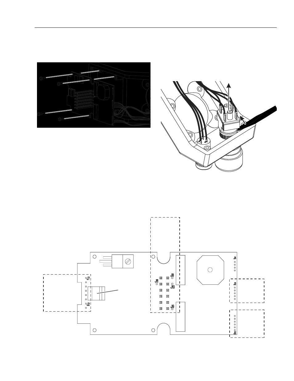
Position the circuit board and unsolder the wires
from the joystick assembly at the J2, J3 and J7 loca-
tions on the circuit board. (See Figure 2-15.)
NOTE: (VP model joystick assemblies prior to S/N- 02996
did not have the drive enable button on the joystick
knob. Wires from this design were attached in the J3
location on the circuit board only.)
5.
With all the joystick wiring unsoldered remove joy-
stick assembly from the control box.
Emergency Stop Switch Removal
1.
Remove the switch part of the emergency stop
switch by carefully prying upward at the corner of
the switch using a straight blade screwdriver. This
will seperate the switch from the reset button part of
the emergency stop button assembly.
2.
Position the circuit board and locate the emergency
stop switch wires connected at locations J8, J9, J10
and J11. Unsolder the four (4) wires to the switch to
remove the switch from the board. (See Figure 2-15.)
Figure 2-15. Platform Control - Circuit Board Component Wiring Connections.
J3
JOYSTICK
WIRING
(5 WIRES)
J2 - J7
JOYSTICK
WIRING
(2 WIRES)
(Later Models With
Enable Button On
Knob Only)
J5
SPEED
CONTROL
SWITCH
(3 WIRES)
TOUCHPAD
SWITCH
CONNECTOR
SOCKET
J8 - J9
J10 - J11
EMERGENCY
STOP
SWITCH
(4 WIRES)