8 drive train troubleshooting, Won’t drive (platform lowered or elevated), Overview of procedure – JLG 15VPSP Service Manual User Manual
Page 70: Check for these obvious conditions first, Joystick powered on, Unit will lift & lower platform, Table 3-7. elevation switch circuit check, Drive train troubleshooting -16, Won’t drive. (platform lowered or elevated) -16, Elevation switch circuit check -16
SECTION 3 - TROUBLESHOOTING
3-16
– JLG Lift –
3120728
3.8
DRIVE TRAIN TROUBLESHOOTING
Won’t Drive (Platform Lowered Or Elevated)
IF MACHINE WON’T DRIVE ONLY WHEN PLATFORM IS ELEVATED, SEE SECTION 4.4
Overview Of Procedure
The following procedures check the components and circuits that feed data to the MC-1 Controller box assuring it is receiv-
ing the proper signals and conditions before engaging the machines’ drive motors.
Check For These Obvious Conditions First:
• Joystick Powered On
• Unit will Lift & Lower Platform
• Machine is not Tilted - (3 LEDs flashing at joystick control)
• PHP Device is not Obstructed - (4 LEDs flashing at joystick control)
• Brakes are not Released - (2 LEDs flashing at joystick control)
• Charger is not Plugged In - (8 LEDs flashing at joystick control)
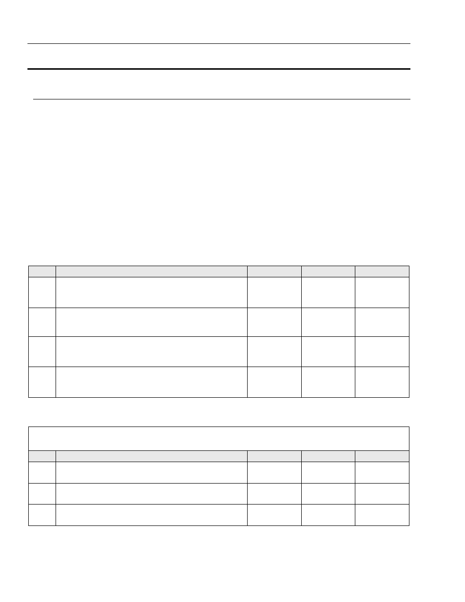
Table 3-6. Won’t Drive. (Platform Lowered or Elevated)
STEP
ACTION
SPEC
YES
NO
1.
Check for ground from elevation limit switch in the X101 connector,
pin 1 (49-5) at MC-1 box.
—
Go to Step 2
Check Elevation
Limit Switch
Circuit (Table 3-7)
2.
Check for ground from charger circuit wire in the X101 connector,
pin 4 (49-7) at MC-1 box. (Perform this check with the charger
unplugged)
—
Faulty Charger
Go to Step 3
3.
Check for ground from brake limit switches in the X105 connector,
pin 11 at MC-1 box.
—
Go to Step 4
Check Brake
Limit Switch Cir-
cuit (Table 3-8)
4.
Check that brakes are releasing, (2 LEDs) when joystick is enabled
& moved forward.
—
Check Drive
Motor Circuit
Check Brake
Switch/Circuit
Table 3-7. Elevation Switch Circuit Check
• Perform these checks at the elevation switch which is located inside the top of mast section-1.
• Check with mast lowered.
STEP
ACTION
SPEC
YES
NO
1.
Check for ground into the switch from ground connection.
—
Go to Step 2
Repair
Connection
2.
Check for ground out of switch to the 49-5 wire.
—
Go to Step 3
Adjust/Replace
Switch
3.
Check for ground from switch to X101, Pin 1.
—
—
Repair Wire or
Connection