JLG E45A_AJ ANSI Service Manual User Manual
Page 56
SECTION 2 - PROCEDURES
2-40
– JLG Lift –
3120765
2.21 FOOTSWITCH ADJUSTMENT
Adjust switch so that functions will operate when pedal is
at center of travel. If switch operates within last 1/4 inch
(6.35 mm) of travel, top or bottom, it should be adjusted.
2.22 POSITRAC/TILT MODULE
When installing a new positrac/tilt module, always ensure
that it is calibrated using the JLG Control System analyzer
before operating the machine. Refer to Section 2.24, JLG
Control System Analyzer Kit Instructions. Use a standard
bubble level in two different directions to ensure that the
machine’s frame is level prior to installing the new posi-
trac/tilt module.
1.
Place the machine on a flat, level surface. Check for
level by placing a bubble level on the frame in both
directions.
2.
Plug in the analyzer (Analyzer - p/n 1600244, Cable -
p/n 1600633) into port J9 on the power module or
port J1 on the platform module.
3.
Use the right arrow key to curse over to "ACCESS
LEVEL 2". Depress Enter.
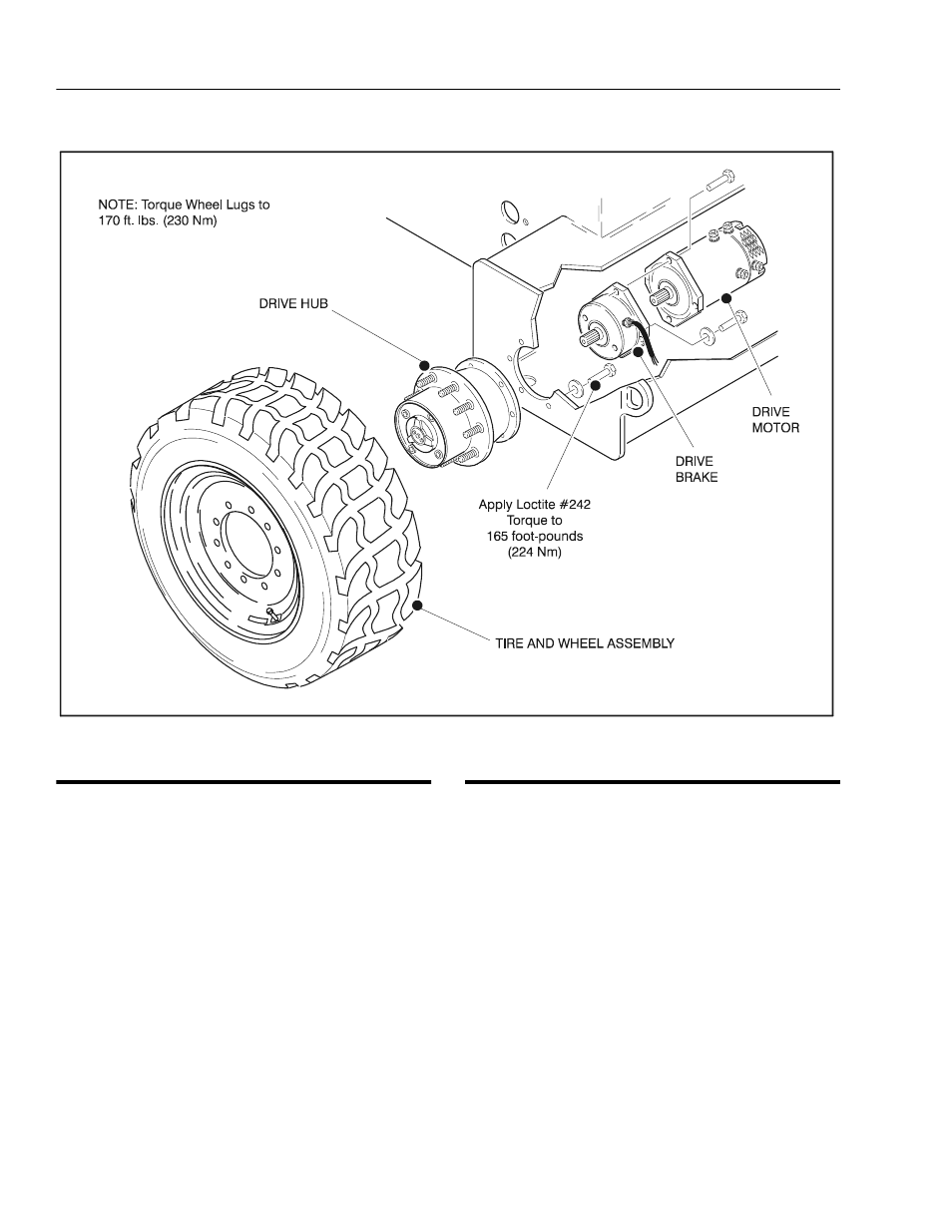
Figure 2-40. Drive Components
Updated 8-30-99