10 load sensing system, Calibration, 11 boom synchronizing procedure – JLG M450 ANSI Service Manual User Manual
Page 124: 12 footswitch adjustment, Load sensing system -12, Calibration -12, Boom synchronizing procedure -12, Footswitch adjustment -12, 10 load sensing system calibration
SECTION 4 - BOOM & PLATFORM
4-12
– JLG Lift –
3121127
3. Align bottom tubes with attach holes in rotator sup-
port. Using a soft head mallet, install rotator support
pin #5 into articulating jib boom and secure with
mounting hardware.
4. Align articulating jib boom with attach hole in articu-
lating jib boom pivot weldment. Using a soft head
mallet, install rotator support pin #4 into articulating
jib boom and secure with mounting hardware.
5. Align bottom tubes with attach holes in articulating
jib boom pivot weldment. Using a soft head mallet,
install rotator support pin #3 into articulating jib
boom pivot weldment and secure with mounting
hardware.
6. Align articulating jib boom pivot weldment with
attach holes in fly boom assembly. Using a soft head
mallet, install pivot pin #2 into fly boom assembly
and secure with mounting hardware.
7. Align the slave leveling cylinder with attach holes in
articulating jib boom pivot weldment. Using a soft
head mallet, install slave leveling cylinder pin #1
into articulating jib boom pivot weldment and secure
with mounting hardware.
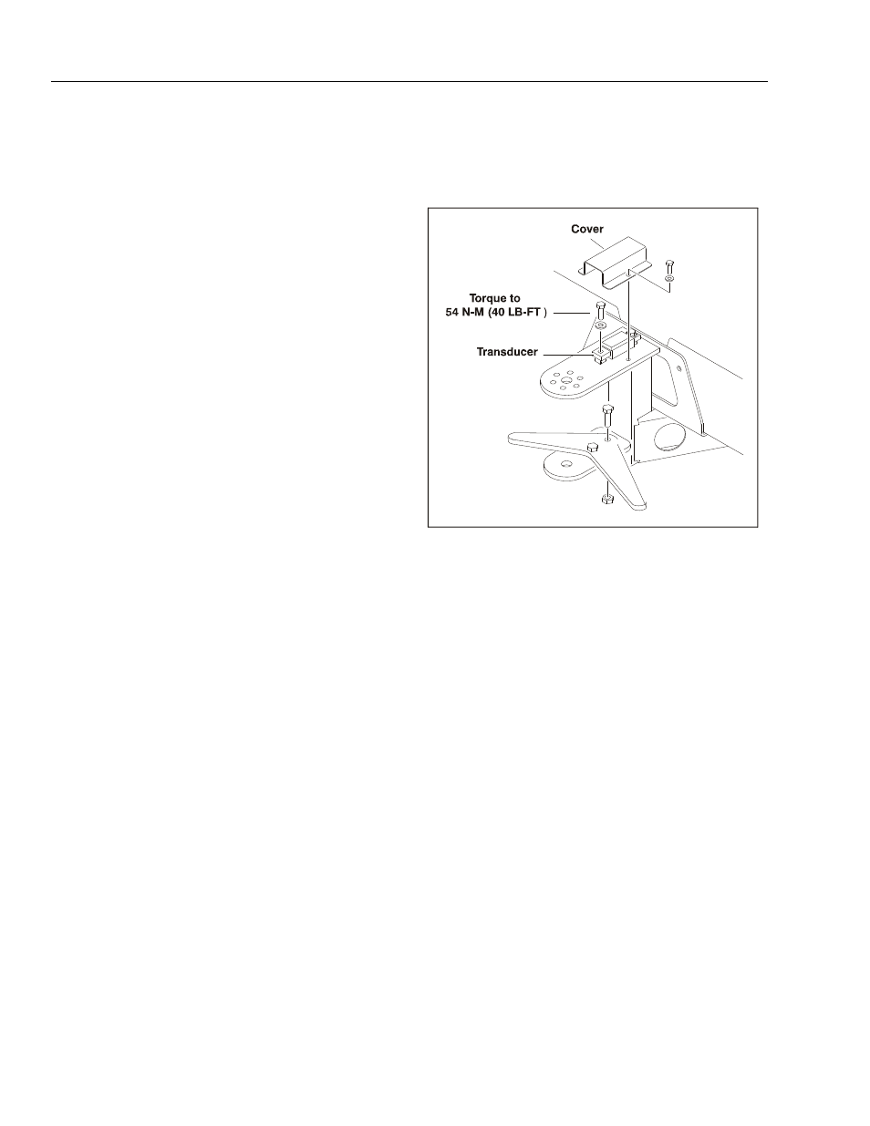
4.10 LOAD SENSING SYSTEM
Calibration
1. Place the machine in a stowed position.
2. Activate both Emergency Stop switches and turn the
Key switch to the platform position.
3. Remove all loads from the basket including opera-
tor.
4. Turn P1 clockwise (in) until the potentiometer begins
to click.
5. Plug the analyzer into port in the platform.
6. Enter password 33271.
7. Select Machine Set-up / Load Cell / 1= Warn Only.
8. Select Diagnostics / System / Load Cell on analyzer.
9. Adjust P2 until the load = 0%.
10. Place 455 LBS. in the center of the basket.
11. Adjust P1 until the load = 100%.
12. Verify that the overload lamp lights continuously and
the alarm sounds continuously during an overload
condition.
13. Remove weight from the basket.
14. Adjust P2 until the load = 0%.
15. Place 455 LBS. in the center of the basket.
16. Adjust P1 until the load = 100%.
17. Remove weight from the basket.
18. Seal potentiometer with fingernail polish.
4.11 BOOM SYNCHRONIZING PROCEDURE
NOTE: If the Lower Boom assembly does not fully lower:
1. Remove all personnel from the platform.
2. Pull the red knob located under the main control
valve.
3. From Ground Control, activate the lift control switch,
raise Lower Boom 6 feet (1.8m).
4. After raising Lower Boom, release the red knob.
5. Activate Lower Boom Down, fully lower boom.
6. Repeat step 1 thru 5 if necessary.
4.12 FOOTSWITCH ADJUSTMENT
Adjust switch so that functions will operate when pedal is
at center of travel. If switch operates within last 1/4 inch
(6.35 mm) of travel, top or bottom, it should be adjusted.
Figure 4-11. Load Sensing System