Assembly, Poly-pak seal installation -7, Cylinder piston nut torque specifications -7 – JLG 500RTS ANSI Service Manual User Manual
Page 23: Holding valve torque specifications -7
SECTION 2 - PROCEDURES
3120696
– JLG Sizzor –
2-7
17.
If applicable, inspect piston rings for cracks or other
damage. Replace as necessary.
Assembly
NOTE: Prior to cylinder assembly, ensure that the proper
cylinder seal kit is used. Refer to the Illustrated Parts
manual.
Apply a light film of hydraulic oil to all components
prior to assembly.
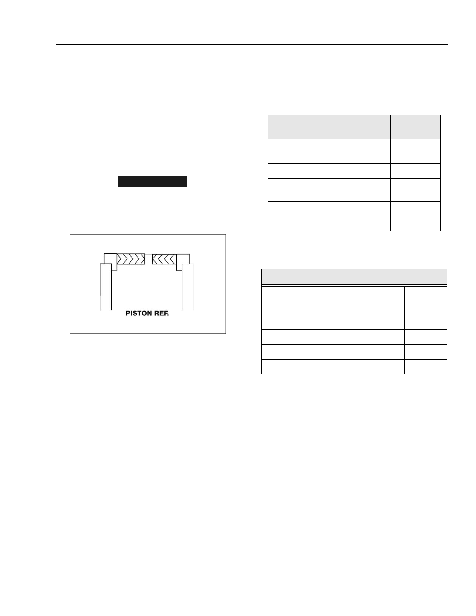
NOTICE
WHEN INSTALLING NEW POLY-PAK TYPE PISTON SEALS (AXLE
LOCKOUT CYLINDER), ENSURE SEALS ARE INSTALLED PROP-
ERLY. REFER TO FIGURE 2-1 FOR CORRECT SEAL ORIENTA-
TION. IMPROPER SEAL INSTALLATION COULD RESULT IN
CYLINDER LEAKAGE AND IMPROPER CYLINDER OPERATION.
1.
Place a new wiper seal and rod seal into the applica-
ble cylinder head gland grooves.
2.
Carefully install the head gland on the rod, ensuring
that the wiper and rod seals are not damaged or dis-
lodged. Push the head along the rod to the rod end,
as applicable.
3.
Carefully slide the piston spacer on the rod. If appli-
cable, align the oil holes in the rod and the spacer.
Secure the spacer, if applicable.
4.
If applicable, correctly place a new o-ring and back-
up rings in the inner piston diameter groove.
5.
Carefully place the piston on the cylinder rod, ensur-
ing that the o-ring and back-up rings are not dam-
aged or dislodged.
6.
Using suitable protection, clamp the cylinder rod in
a vise or similar holding fixture as close to the piston
as possible.
7.
Push the piston onto the rod until it abuts the spacer
end, apply locktite # 242 and install the attaching
nut. Refer to Table 2-1, Cylinder Piston Nut Torque
Specifications.
NOTE: On the Steer Cylinder, the rod and piston are all one
unit.
8.
Prior to setscrew installation spot drill rod before
installing the setscrew(s) which secure the piston
attaching nut to the diameter groove.
9.
Remove the cylinder rod from the holding fixture.
10.
Place new o-rings and seals in the applicable out-
side diameter grooves of both the piston and the cyl-
inder head.
Figure 2-1. Poly-Pak Seal Installation
Table 2-1. Cylinder Piston Nut Torque Specifications
Description
Nut Torque
Value
Setscrew
torque Value
Lift Cylinder
400 ft lb
(542 Nm)
100 in lb
(12 Nm)
Lockout Cylinder
N/A
N/A
Level Cylinder
400 ft lb
(542 Nm)
100 in lb
(12 Nm)
Platform Ext. Cylinder
N/A
N/A
Steer Cylinder
N/A
N/A
Table 2-2. Holding Valve Torque Specifications
Description
Torque Value
Sun - 7/8 hex M20 x 1.5 thds
30 - 35 ft lb
41 - 48 Nm
Sun - 1-1/8 hex 1 - 14 UNS thds
45 - 50 ft lb
61 - 68 Nm
Sun - 1-1/4 hex M36 x 2 thds
150 - 153 ft lb
204 - 207 Nm
Racine - 1-1/8 hex 1-1/16 - 12 thds
50 - 55 ft lb
68 - 75 Nm
Racine - 1-3/8 hex 1-3/16 - 12 thds
75 - 80 ft lb
102 - 109 Nm
Racine - 1-7/8 hex 1-5/8 - 12 thds
100 - 110 ft lb
136 - 149 Nm