Maintenance, Calibration – Snorkel A38E-sn004500+ User Manual
Page 59
Maintenance
Section
4-29
A38E Work Platform
4.21
Storage of the dead load (tare)
and the limit value (alarm)
1. MRW LIMIT has been mounted and the
control cable is connected.
2. The supply voltage has been applied and
the system is switched on.
3. The platform is unloaded and it has been
ensured that the platform has no base
4. Remove the program connector’s dust
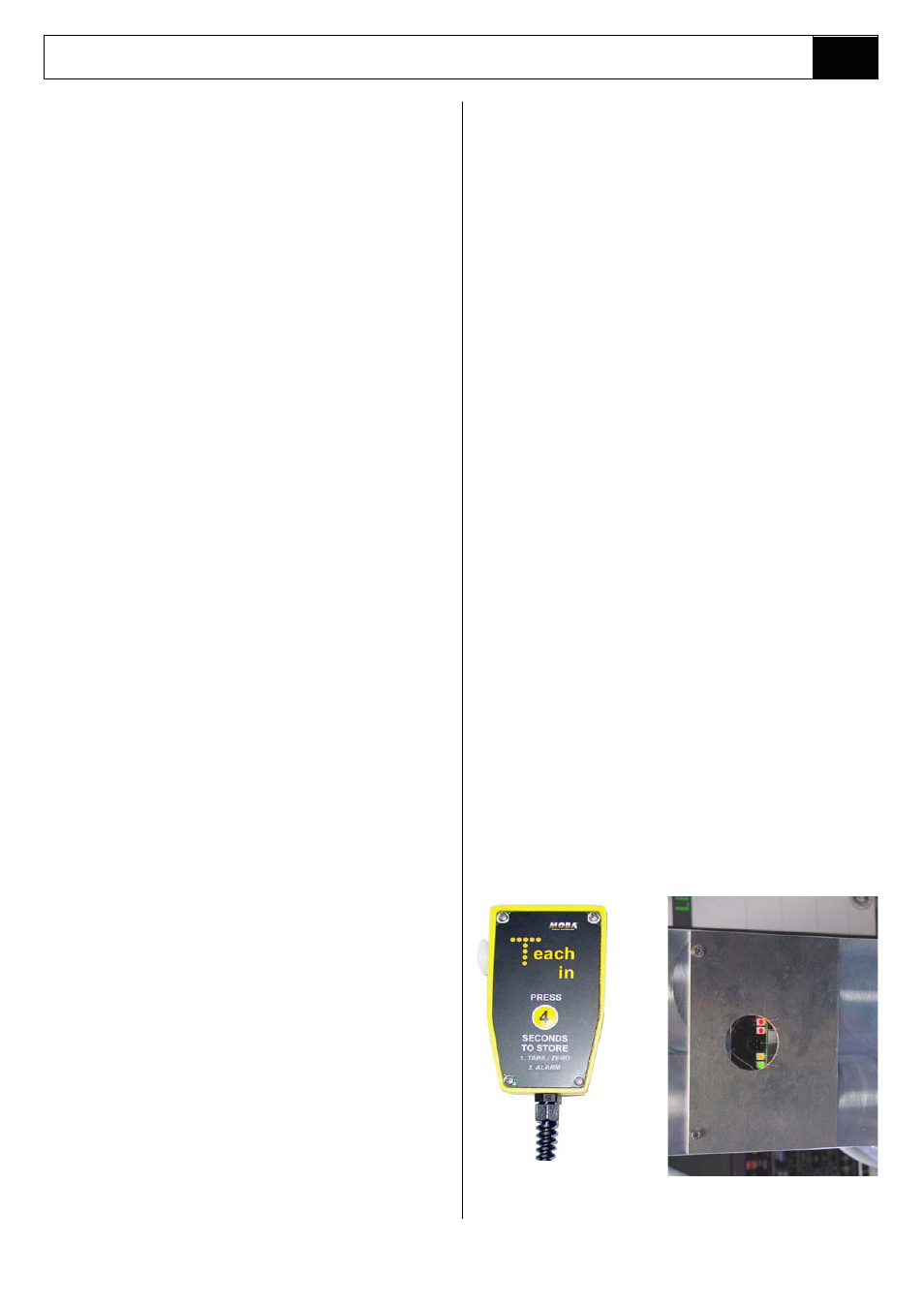
5. Connect the Teach in Handset.
6. After a check-up the “ T“ in the label of the
Teach in Handset flashes with a frequency
contact.
protection cap.
of 5Hz.
4.21 START UP / CALIBRATION OF
THE MOBA OVERLOAD CELL.
START UP
Error LED
Alarm LED
Interface Connector
Zero/Tare LED
Power LED
• If the "T" at the label of the Teach in Handset
does not flash but light up constantly, this may
indicate an error that does not allow teaching.
1. System alarm The right red LED at
the MRW
2. Motion The determined weight fluc
tuates too
LIMIT lights up! (check system)
much! (check platform)
7. After the key labeled with “4“ is pressed for 4
8. The platform has to be loaded with an alarm
weight (100%) and it has to be ensured that the
platform has no base contact. The Handset stays
connected! The “T“ in the label of theTeach in
Handset starts flashing with a low frequency of
approx.1Hz.
•
The load has to be at least 10kg above the tare
weight, otherwise the “T“ in the label of theTeach
in Handset will not start flashing!
9. The key labeled with “4“ is pressed again for 4
seconds until the “T” of the Teach inHandset
lights up contstantly.
seconds, the “T” of the Teach in Handset lights
up constantly. In older versions (before 2010),
the “T“ in the label of the Teach in Handset
subsequently starts flashing with a low frequency
of approx.1Hz.
10. Disconnect the Teach in Handset.
11. The alarm is activated.
12. Slightly release and after 4 seconds reload the
platform again to check up the switch point.
13. After the alarm weight has been unloaded, the
orange LED at the MRW has to be activated
(+/- 15kg dead load control).
14. Close the program connector with the dust
protection cap.
15. Stick label stored and test r with the dust
protection cap.
16. The programming process is completed.
CALIBRATION
1. MRW LIMIT has been mounted and the control
cable is connected.
2. The supply voltage has been applied and the system
has been switched on.
3. The platform is unloaded and it has been ensured
that the platform has no base contact.
•
If the orange LED (zero/tare) at the MRW is activated,
a calibration is not necessary, but if the LED is not
activated, please continue with point 4.
4. Remove the program connector’s dust protection cap.
5. Connect the Teach in Handset.
6. After the check-up the “T“ in the Teach in Handset’s
label flashes with a frequency of 5Hz.
• If the "T" at the label of the Teach in Handset does not flash
but light up constantly this may indicate an error that does
not allow teaching.
1. System alarm The right red LED at the MRW LIMIT
lights up! (check system)
2. Motion The determined weight fluctuates much!
(check platform)
7. The key labeled with “4“ is activated for 4 seconds,
the “T” of the Teach in Handset lights up constantly.
In older versions (before 2010) after lighting up
constantly, the “T“ in the label of the Teach in Handset
starts flashing with a low frequency of approx.1Hz.
8. Disconnect the Teach in Handset.
9. Now the orange LED [zero/tare] at the MRW has to
be activated (+/- 15kg dead load control).
10. If the orange LED (zero/tare) at the MRW is not
activated, please repeat point 5. – 9.
11. Close the program connector with the dust
protection cap.
12. Stick label „stored and tested“ over the program
connector (included in delivery).
13. The programming process is completed.