Passage through a doorway, Lowering, Raising – Snorkel UL40 User Manual
Page 6
6
Passage Through A Doorway
The UL32 and UL40 are equipped with a castered
rear Tilt Back assembly. When the unit is tilted
back onto this support frame, the overall height is
reduced to allow the unit to pass through a stan-
dard doorway.
LOWERING
Before tilting the machine onto the rear Tilt
Back assembly be sure the retaining pin is
fully inserted with the hair pin retainer
installed and the cylinder assembly is fully
extended.
DO NOT drop Tilt Back frame.
Keep out from under Tilt Back frame and
machine when tilting.
1. Be sure area is clear of personnel and obstructions.
2. While holding Tilt Back frame, remove the hair
pin retainer and the retaining pin (Figure 8).
3. Lower the Tilt Back frame until the hole in the
cylinder assembly aligns with the upper
mounting bracket pin hole. Secure the cylinder
assembly to the upper mounting bracket using
retaining pin and hair pin retainer (Figure 8).
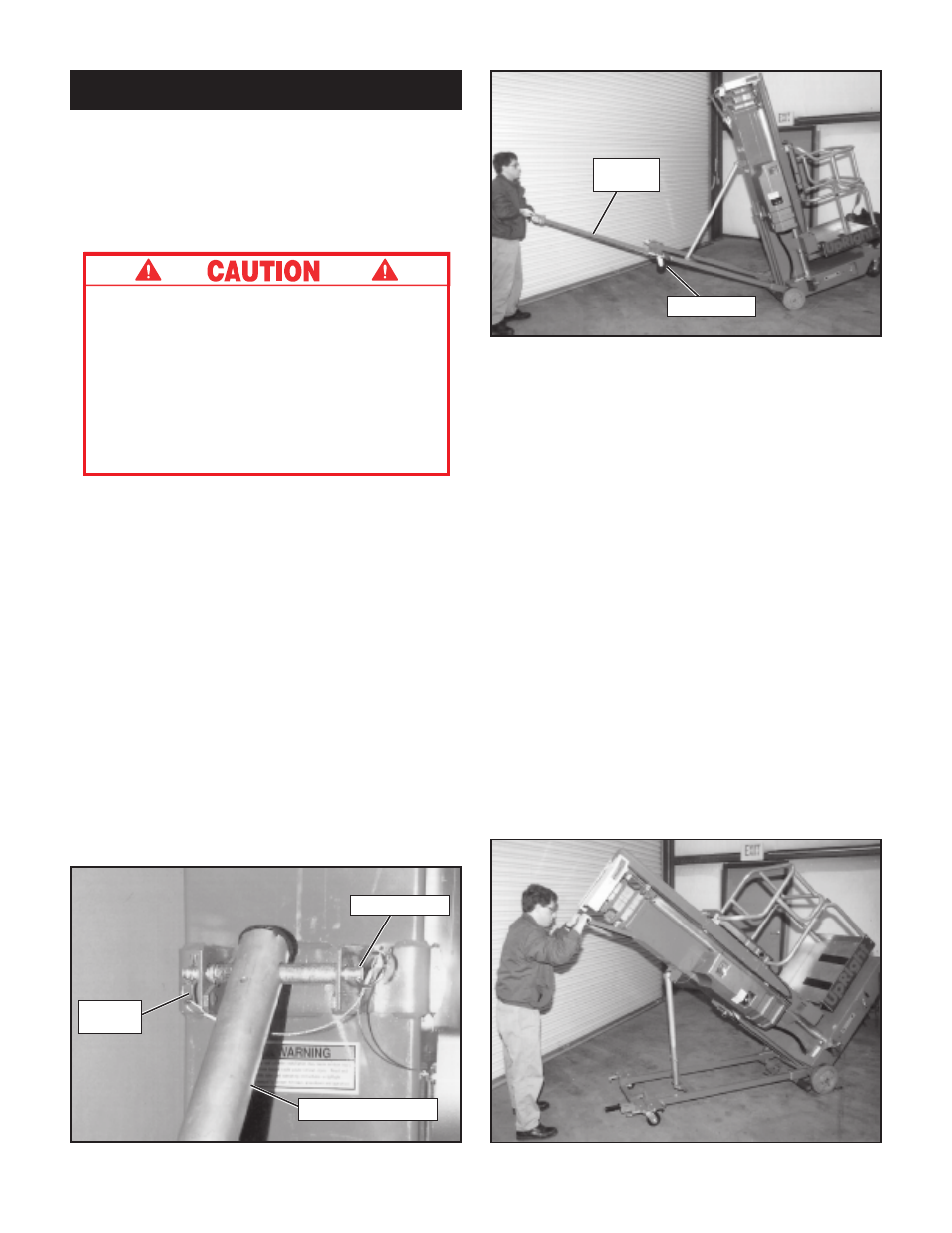
4. Extend Tilt Back Handle to the tilt/lift position
by releasing locking pin and pulling handle out
of the Tilt Back assembly until the locking pin
engages (Figure 9).
5. Push down on the Tilt Back Handle until the
unit comes to rest on the Tilt Back frame. As the
mast tilts back, counterbalance the machines
weight by increasing upward force on end of Tilt
Back Handle (Figure 9). This allows machine to
gently come to rest on Tilt Back casters.
Figure 8: Cylinder secured with retaining pin
Figure 9: Lowering and raising with Tilt Back
Handle
Figure 10: Compressing cylinder assembly
6. Pull down on the handle on the back of the mast
to compress the cylinder assembly (Figure 10).
7. Return Tilt Back Handle to storage position
making sure locking pin engages handle.
RAISING
1. Lift up on mast handle to extend cylinder assembly.
2. Fully extend the Tilt Back Handle until the
locking pin engages.
3. Lift up on the Tilt Back Handle. As the mast
approaches vertical, counterbalance machines
weight by increasing the downward force on
end of Tilt Back Handle (Figure 9). This allows
machine to settle gently on the front casters.
4. Return Tilt Back Handle to storage position
making sure locking pin engages handle.
5. While holding Tilt Back frame, remove retain-
ing pin and raise Tilt Back assembly to the
stowed position. Secure with the retaining pin,
making sure pin is fully inserted and hair pin
retainer installed.
Hair Pin
Retainer
Cylinder Assembly
Retaining Pin
Tilt Back
Handle
Locking Pin