Outrigger installation, Operation – Snorkel UL40 User Manual
Page 2
2
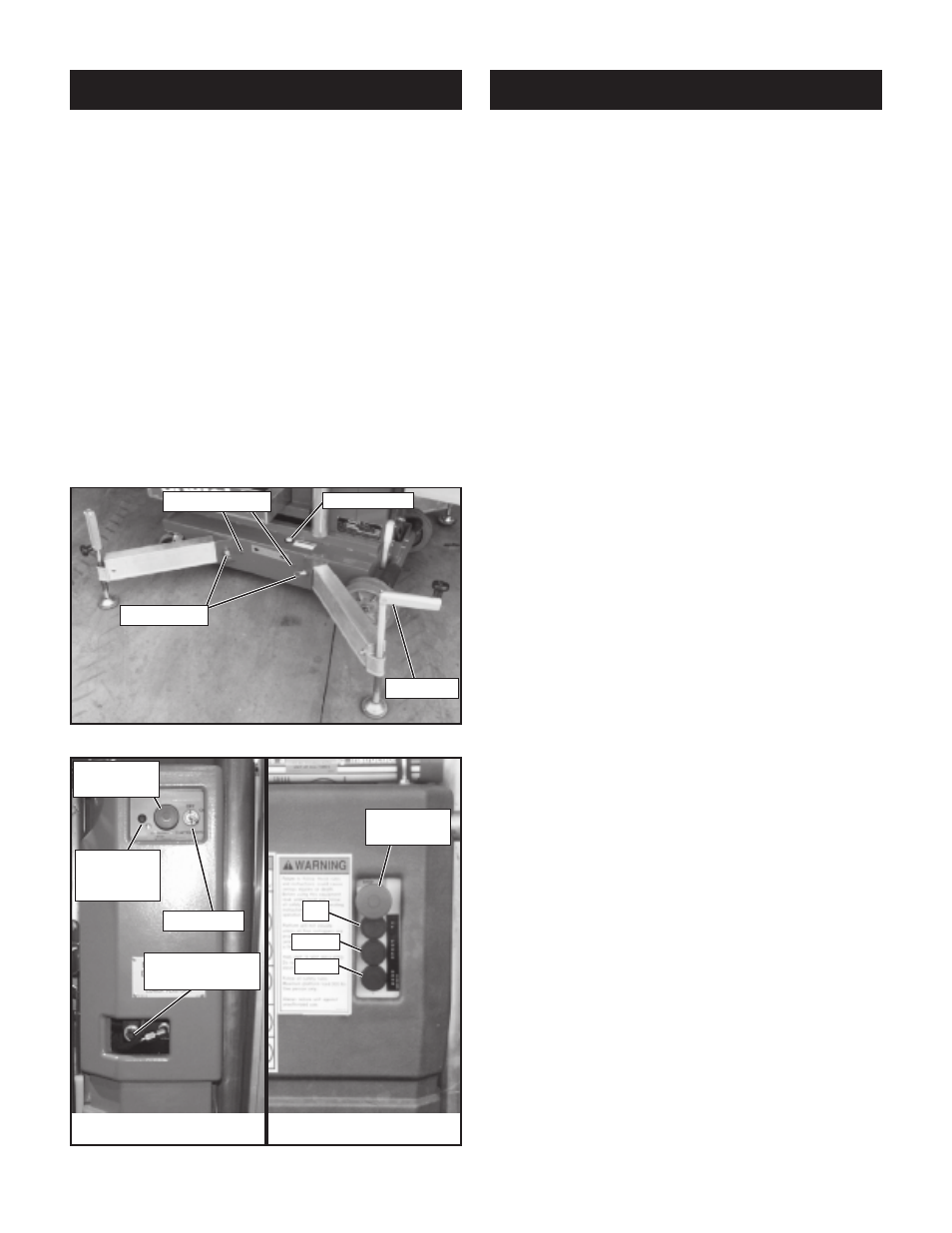
Outrigger Installation
1. Remove the outriggers from storage locations
on sides of mast.
2. Insert into outrigger socket in base (Figure 1).
3. Push in until locking pin engages hole in end of
outrigger. Pull outward on outrigger to ensure
engagement.
4. Repeat the above steps for all other outriggers.
Make sure all four (4) locking pins are engaged.
5. Level the base, centering the bubble in the orbit
level on the base by adjusting the screwjacks at
the end of each outrigger (Figure 1). DO NOT
release the tension on an outrigger, by turning
counterclockwise, to level base.
6. All four (4) screwjack pads must be in solid
contact with a firm surface and each outrigger
indicator light must be lit before the platform
is elevated.
Operation
Before operating UL Lift insure that: the operator has
been thoroughly trained on this machine, the opera-
tor has read, fully understands and follows this
Operator Manual and the Scaffold Industry
Association's MANUAL OF RESPONSIBILITIES, the
unit has been properly set up with all four (4) outrig-
gers properly installed and the base leveled, and the
machine has passed the Safety Interlock Test.
Note: Platform will not elevate unless all four
outriggers are properly installed with screwjack
pads firmly in contact with floor and each outrig-
ger indicator lamp lit.
1. Check for external damage to the mast.
2. For AC units connect power unit plug to exten-
sion cord (12 ga. (1.5 mm²) conductor minimum
and 50 ft. (15 m) in length maximum).
Connect extension cord to properly grounded
outlet of proper voltage and frequency.
3. Turn Key to ON, Key Switch is located on the
left side of the mast (Figure 2).
4. Pull out on Lower Emergency Stop Button,
located on the left side of the mast (Figure 2), to
turn switch ON. In the event of an emergency
push the button in to cut power to all controls.
5. Enter the platform by pulling out on the locking
pin and lifting up on the upper half of the cage.
6. Lower upper half of the cage after entering
platform making sure locking pin is engaged.
7. Check that the area above the platform is clear
before elevating the platform.
8. Pull out on Emergency Stop Button, located on
platform control panel (Figure 2). In the event of
an emergency push the button in to cut power to
all controls.
9. Push both the middle and top buttons (POWER
and UP), on the Control Box (Figure 2), at the
same time to elevate the platform. Release the
buttons to stop.
10. Check that the area below the platform is clear
before lowering the platform.
11. Push both the middle and bottom buttons
(POWER and DOWN) at the same time to lower
the platform. Release the buttons to stop.
12. After use, secure unit from unauthorized use by
turning Key Switch to OFF and remove key.
Figure 1: Installing outriggers
Figure 2: Controls
Platform Controls
Base Controls
Indicator Light
Bubble Level
Locking Pin
Screwjack
Key Switch
Emergency
Stop Button
Down
Power
Up
Emergency
Lowering Valve
Optional
Emergency
Down LED
Emergency
Stop Button