Caution – Snorkel TB47J User Manual
Page 49
Chapter 8 – Operation
TB47J – 0075182
45
3. Place the fuel switch in the LPG position.
To switch from LPG to gasoline with the engine running:
1. Place the fuel switch in the gasoline position.
2. Close the shut-off valve on the LPG tank.
Air Line
The optional air line may be used to conduct air for tool
operation at the platform. The input connector is at the
rear of the chassis and the output connector is at the
platform on the rotator guard. The maximum working pres-
sure of the line is 250 psi (1,723 kPa).
The air line may be used to conduct fluids such as water
or antifreeze. Contact Snorkel for compatibility informa-
tion before using the air line to conduct other fluids.
A
Caution
Fluid in the air line can damage some air tools or
freeze and damage the line. Drain and blow out the
air line after using it to conduct fluids.
Use the following procedure to drain the air line.
1. Close the input connector on the chassis.
2. Open the output connector at the platform.
3. Raise the boom slightly above horizontal.
4. Open the input connector on the chassis.
5. Allow the fluid to drain from the line.
6. Lower the boom and close both connections.
Driving Lights
The optional driving lights are for use in dimly lit areas
and are not intended for driving on public roadways. There
are two headlights at the front of the chassis and two
blinking taillights at the rear of the chassis.
The lights are operational when the battery disconnect
switch and the master switch are turned on.
Note
Working with the driving or platform work lights on, while
the engine is off, can discharge the batteries enough
that the engine will not start or the emergency power sys-
tem will not operate. If the engine cannot be left running
while the lights are on, start and run the engine for at
least 15 minutes each hour.
Platform Work Lights
The optional platform work lights are located on the top
rail of the platform. The direction a light points can be
adjusted by using two
1
/
2
″ wrenches to loosen the clamp
below the light.
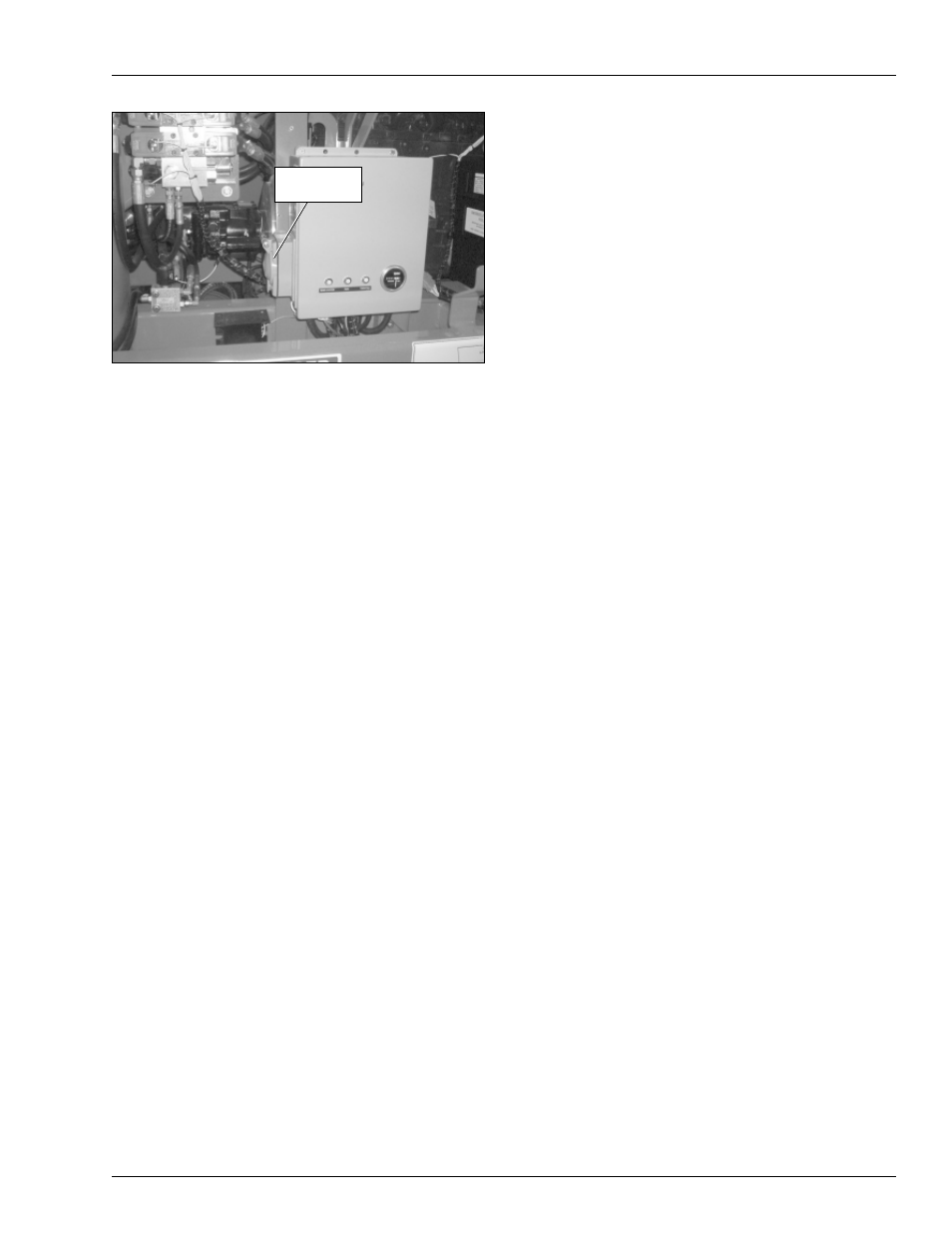
Figure 8.5 – Wiring Box
A
Caution
Cold hydraulic oil does not flow well and may pro-
duce improper generator output voltage. Improper
outlet voltage can damage some electrical power
tools and equipment. Warm the hydraulic oil be-
fore operating the generator.
Do not operate the generator unless the hydraulic oil tem-
perature is at least 100°F (38°C). Refer to Cold Weather
Start-Up for a hydraulic oil warm-up procedure.
Use the following procedure to supply power to the elec-
trical power outlet if the machine is equipped with the
optional generator.
1. Plug the generator cord into the outlet on the left
side of the wiring box.
2. Start the engine and place the machine/generator
selector switch, on the front of the upper control, panel
in the generator position.
The engine will run at high idle while the generator is
operating. The generator will continue to operate as long
as the engine is running and the switch is in the genera-
tor position.
Dual Fuel
The dual fuel switch is located on the front of the lower
control panel.
Before starting the engine, place the fuel switch in the
gasoline or the LPG position. Open the shut-off valve on
the LPG gas tank if using LPG. Always keep the LPG
tank shut-off valve closed when not using LPG.
To switch from gasoline to LPG with the engine running:
1. Open the shut-off valve on the LPG tank.
2. Place the fuel switch in the off position until the en-
gine starts to die.
Power-Input
Connector