Snorkel TB42J User Manual
Page 35
Chapter 7 – Prestart Inspection
TB42J – 0172310
31
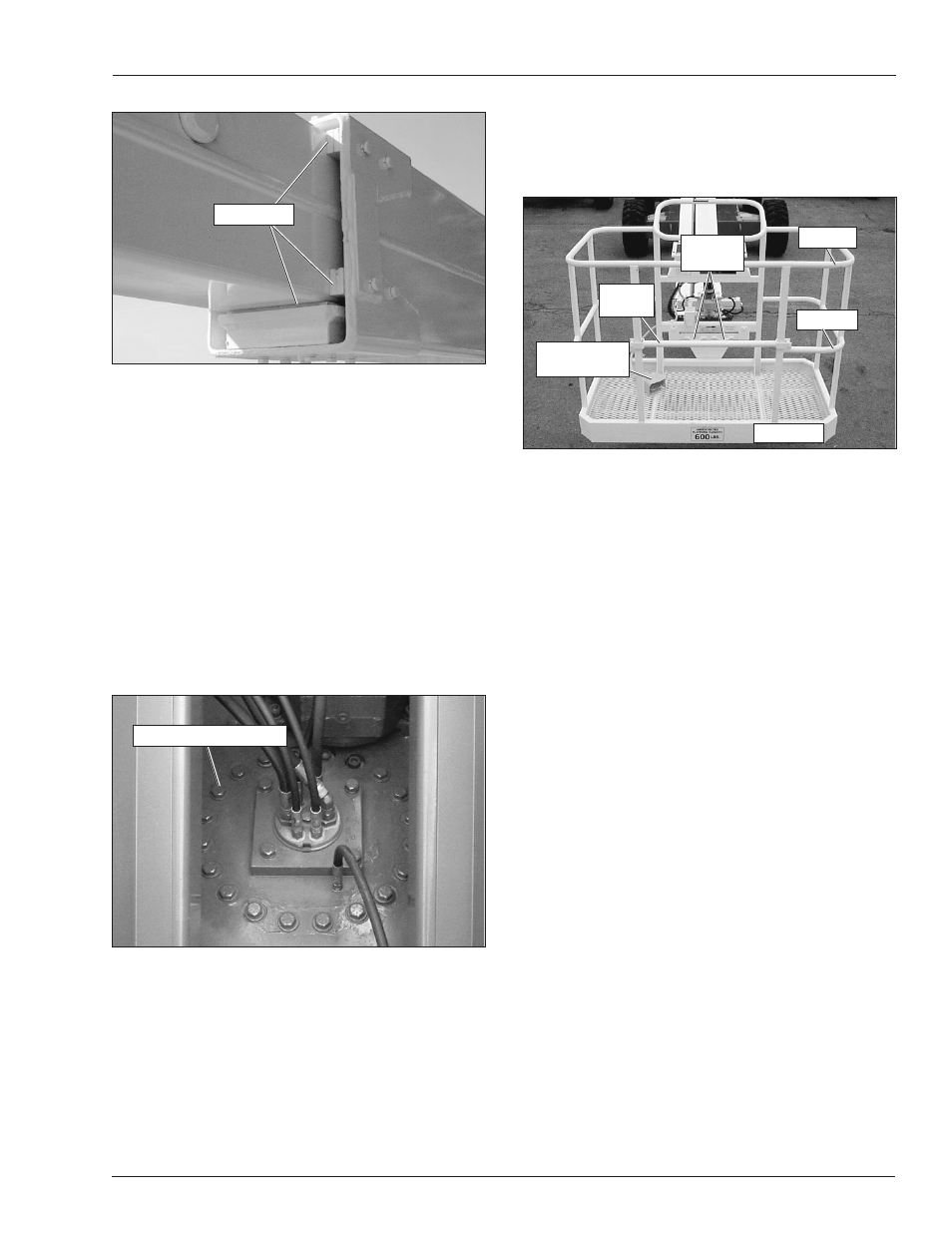
Guardrail System
The guardrail system (refer to Figure 7.18) includes the
top rail, mid rail, toeboards and a gravity gate or optional
swinging gate.
Figure 7.18 – Guardrail System
Inspect all components of the guardrail system. The rails
and toeboards must all be in place and free of any dam-
age or deformation. Visually check the rail and toeboard
welds for cracks. All bolts and nuts fastening the plat-
form in place must be present and not show any signs of
looseness.
Inspect the gravity gate to be sure it is present, is not
damaged, and moves freely.
Inspect the optional swinging gate to see that it swings
freely, closes firmly, and is not deformed in any way. Make
sure the spring closes and secures the gate when the
gate is closed.
Lanyard Anchors
There are two lanyard anchors below the upper control
panel (refer to Figure 7.18).
Visually inspect the lanyard anchors to make sure they
are in place, are not deformed and are securely fastened
to the platform.
Operating Controls
Use the following procedure to operate the machine from
the upper controls.
1. Turn the battery disconnect switch on.
2. At the lower controls, place the emergency stop
switch and the master switch in the on position. Place
the controls switch in the platform position.
3. At the upper controls (refer to Figure 7.19), pull the
emergency stop button out.
Figure 7.16 – Slide Pads
Use the lower controls to raise the main boom to horizon-
tal. Extend the tip boom about 1
′
(30 cm). Visually in-
spect the slide pads to make sure they are in place and
are not obviously loose.
Inspect the surface where the pads contact the tip boom.
The paint must be in place with no signs of bare metal.
Fasteners
Visually inspect all fasteners to see that none are miss-
ing or loose.
Pay particular attention to all of the bolts, nuts, rollpins,
collars, and snap rings that connect the booms and cyl-
inders. They should all be present, tight, and not dam-
aged in any way.
Figure 7.17 – Rotation Bearing Bolts
Inspect the rotation bearing bolts to ensure that none are
missing, damaged, or loose.
Upper Control Station
Inspect the platform and upper controls only if all func-
tions operated properly from the lower controls.
Slide Pads
Rotation Bearing Bolts
Toeboard
Top Rail
Mid Rail
Gravity
Gate
Lanyard
Anchors
Platform Foot
Switch