Caution warning, Transportation – Snorkel TL33-sn1001-1946 User Manual
Page 7
7
CONTROL FROM GROUND LEVEL
1.
Chassis Controls are fitted at the base of the
Elevating Assembly. These should only be used
when no operator is in the Platform (for
maintenance/service or inspection purposes), or if
the operator has become incapacitated.
2.
It should be noted that in order to activate any of the
Lower Control Toggle Switches the Keyswitch, also
located on the Lower Controls, must be turned
clockwise to the CHASSIS position.
3.
Use the appropriate toggle switch to raise or lower
Boom 1, Boom 2 or rotate as required.
AFTER USE EACH DAY
1.
Ensure that the Platform is fully lowered.
2.
Park the machine on a level surface, preferably
undercover, secure against vandals, children or
unauthorised operation. Apply the Hand Brake.
3.
Turn the Keyswitch to OFF and remove the key to
prevent any unauthorised operation.
4.
Recharge the batteries in accordance with the
instructions on Page 9.
Transportation
BY FORKLIFT
The TL33 is not designed to be forklifted, and does
not have provision on the Chassis to allow this
method of lifting. UpRight recommends the
procedure below for handling the machine.
BY CRANE
See specifications (Page 16) for the weight of
the work platform and be certain that lifting
apparatus is of adequate capacity to lift the
platform.
The TL33 may be lifted by an overhead hoist/crane in the
following manner:
Four lifting straps capable of safely supporting the total
weight of the TL33 (2,734 lbs (1,240 Kg)), and at least 8
feet (2.5 m) long are required. This minimum length is
important to ensure the correct lifting angle. The straps
should be positioned as shown in Figure 6.
The four lifting straps (Positions 1, 2, 3 & 4) should be
positioned at the points indicated in Figure 6. Care must be
taken to ensure the straps do not interfere with any other
parts of the TL33.
The two rear lifting straps should be positioned between
the Outrigger Quadrant Plates and the Chassis Main
Member as indicated by positions 1 and 2. Care must be
taken that these two straps will not damage the cable for
the Outrigger Limit Switches.
The two front lifting straps should be positioned under the
Tow Bar Weldment, directly in front of the brake cable
anchor plate, as indicated by positions 3 and 4. Note that
the two straps are essential at this position as one must
pass each side of the Lower Boom, on the interior sides of
the Tension Bar Weldments.
CAUTION
WARNING
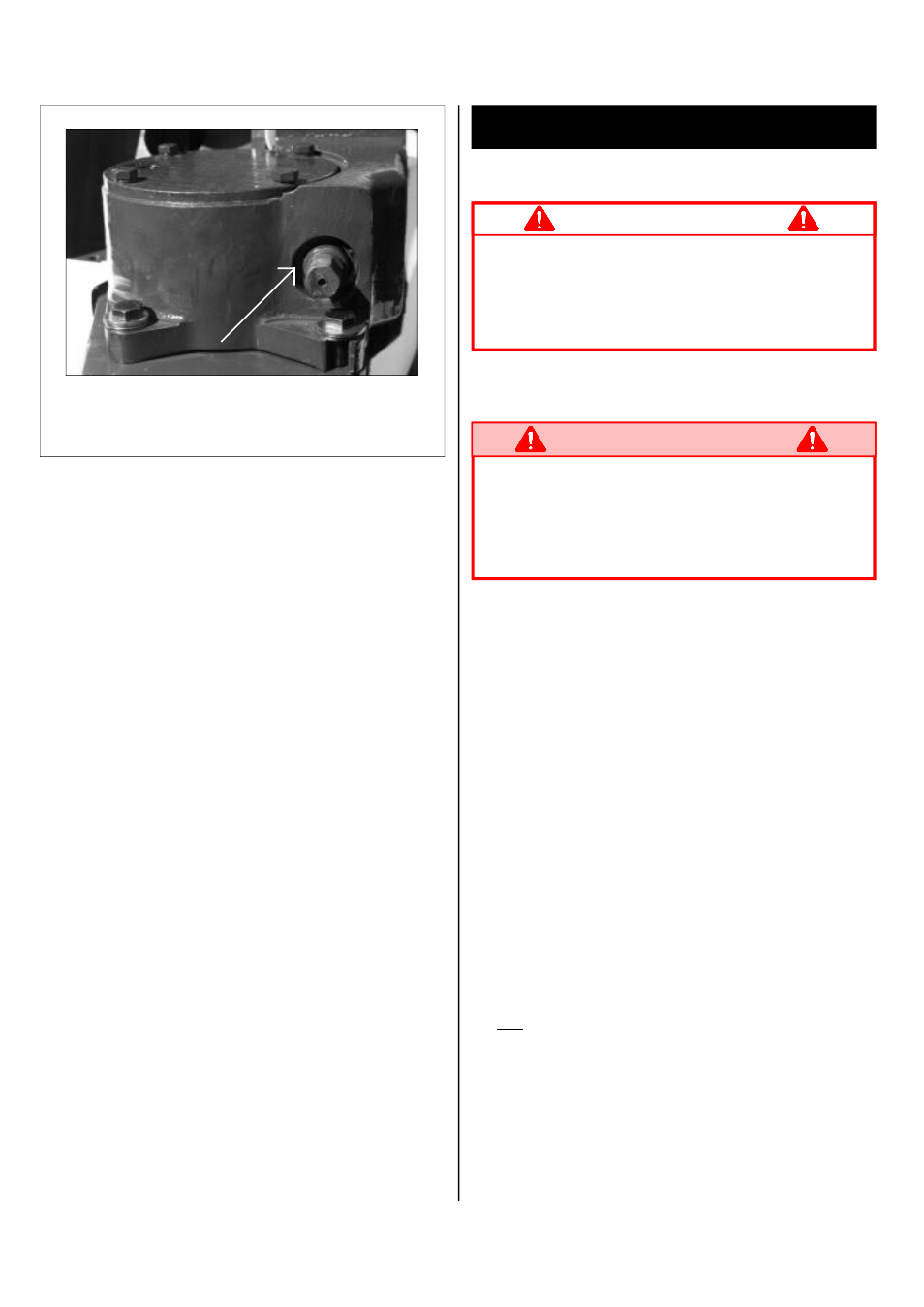
Figure 5: Manual Rotation
To rotate the Elevating Assembly first apply a 17 mm
(13 mm) socket wrench to the shaft and turn to rotate
the Elevating Assembly. When finished remove the
wrench.
Gerabox Manual
Rotation Shaft