Operation, Travel with platform lowered, Steering – Snorkel SL30SL-sn9600-11199 User Manual
Page 4
4
9. Push Chassis Lift Switch to UP position and
elevate platform. The platform should only elevate
to the interlock height, about 2.44 m (8 ft.) above
the ground, and the Tilt Alarm should sound. If the
platform continues to elevate and/or there is no
alarm STOP and remove the machine from
service until repaired.
10. Lower the platform with the Chassis Lift Switch.
11. Enter the platform. Using the bubble level as a
guide level the platform with the Side/Side and
Fore/Aft Switches. Dismount platform.
12. Fully elevate platform using Chassis Lift Switch.
13. Visually inspect the elevating assembly, lift
cylinder, cables and hoses for damage or erratic
operation. Check for missing or loose parts.
14. Lower the platform partially by pushing Chassis
Lift Switch to DOWN, and check operation of
the audible lowering alarm.
15. Push down on the Chassis Emergency Lower-
ing Switch to check for proper operation. Once
the platform is fully lowered, release the switch.
16. Push the Chassis Emergency Stop Button.
17. With only one Emergency Stop Button pushed
down, in the OFF position, operate a control to
verify that the Emergency Stop Switch is func-
tioning. Repeat the test with only the other
Emergency Stop Switch Button OFF. If any
function operates with either Emergency Stop
Switch in the OFF position STOP and remove
the machine from service until it is repaired.
18. Close and secure module covers.
19. Turn the Controller Key Switch counterclock-
wise to OFF.
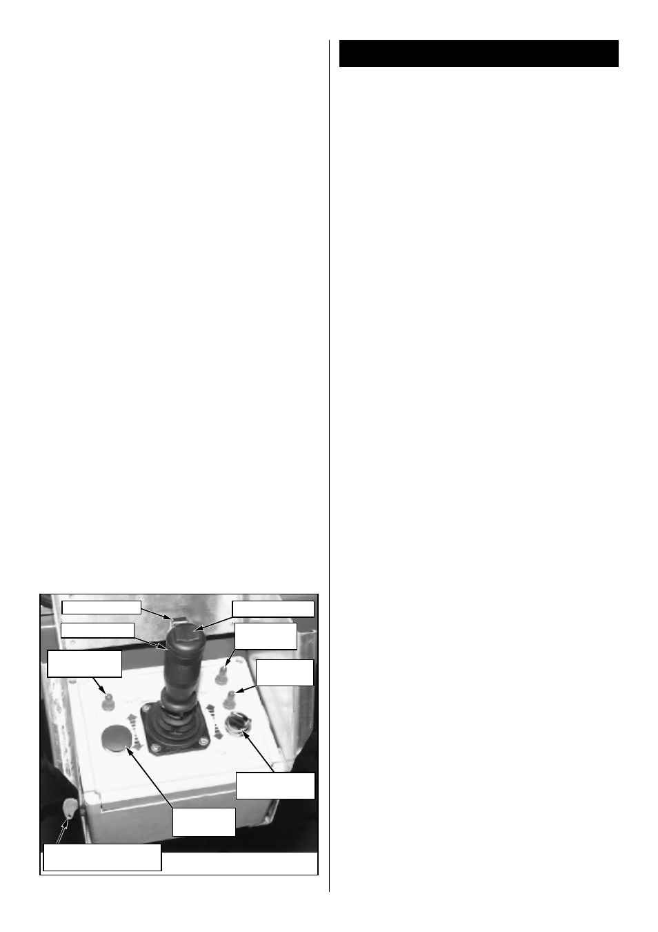
Figure 2: Controller
Interlock Lever
Speed Range
Switch
Steering Switch
Control Lever
Fore/Aft Tilt
Switch
Left/Right
Tilt Switch
Key Switch (on right
side for Diesel Models)
Emergency
Stop Switch
Drive/Level/Lift
Switch
Operation
Before operating work platform, ensure that the
pre-operation and safety inspection has been
completed, any deficiencies have been corrected
and the operator has been thoroughly trained on
this machine.
Travel With Platform Lowered
1. Verify Chassis Emergency Stop Switch is in the
ON position, pull the button out.
2. After mounting platform, close and latch gate.
Check that guardrails are in position and prop-
erly assembled with fasteners properly torqued.
3. Check that route is clear of persons, obstruc-
tions, holes and drop-offs and is capable of
supporting the wheel loads.
4. Check clearances above, below and to the
sides of the platform.
5. Pull Controller Emergency Stop Button out to
ON position.
6. Turn Controller Key Switch fully clockwise to
start the engine, releasing the key once the
engine starts.
Note: On Diesel Models, if the engine is cold,
turn the key fully counterclockwise and hold for
30 seconds to engage the glow plugs.
7. Set the Drive/Lift Speed Range Switch to HIGH
TORQUE.
8. Grasp the Control Lever so the Interlock Lever
is depressed (releasing the Interlock Lever cuts
power to Controller). Slowly push or pull the
Control Lever to FORWARD or REVERSE to
travel in the desired direction. The farther you
push or pull the Control Lever from center the
faster the machine will travel.
9. While moving, push the Drive/Lift Speed Range
Switch to HIGH SPEED for travel on level
surfaces or to HIGH TORQUE for climbing
grades or traveling in confined areas.
Steering
Push the Steering Switch RIGHT or LEFT to turn
the wheels. Observe the tyres while maneuvering
to insure proper direction.
Note: Steering is not self-centering. Wheels
must be returned to the straight ahead position
by operating the Steering Switch.