Caution, Warning – Snorkel PUSH10 User Manual
Page 16
Inspection and Maintenance Schedule
14
PUSH6/PUSH8/PUSH10 – 0120843
Inspection and Maintenance Schedule
Caution
Frequency and extent of periodic examinations may
depend on national regulations.
The Complete Inspection consists of periodic visual and
operational checks, along with periodic minor adjustments
that assure proper performance. Daily inspection will pre-
vent abnormal wear and prolong the life of all systems.
The inspection and maintenance schedule should be
performed at the specified intervals and after prolonged
periods of storage before returning the machine to ser-
vice. Inspection and maintenance shall be performed by
personnel who are trained and familiar with mechanical
and electrical procedures.
Warning
Before performing preventative maintenance, famil-
iarize yourself with the operation of the machine.
Always block the scissors structure whenever it is
necessary to perform maintenance while the platform
is elevated.
The daily preventative maintenance checklist has been
designed for machine service and maintenance. Please
photocopy the Daily Preventative Maintenance Checklist
and use the checklist when inspecting the machine.
Keep the charger dry.
1. At the lower controls, turn the control selector switch
to the off position.
2. Open the component tray to access the battery.
Remove the caps from the battery.
3. Visually check the battery fluid level making sure the
level is within 6 mm (¼″) of the bottom of the filler neck
inside each hole. If needed, add distilled water.
4. Tightly replace the caps on each battery and replace
and latch the battery tray covers.
5. Place the battery charger mode selector, on the lower
control panel, in the appropriate position for power
source being used.
Move the toggle switch to the left for operation
on 110V circuits.
Move the toggle switch to the right for operation
on 230V240V circuits.
6. Plug the battery charger into a properly grounded
outlet (100-240 volt AC, 50/60 Hz) using a 3 conduc-
tor, 1.5 mm (12 gauge) or larger extension cord. The
extension cord must be as short as possible and in
good electrical condition.
Note
The aerial platform will not operate while the battery
charger is plugged in.
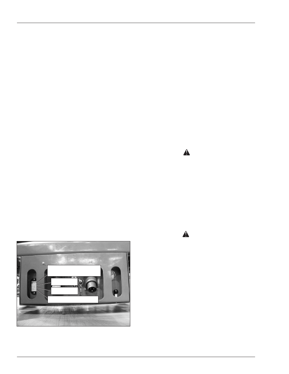
7. Visually inspect the battery charge indicator for proper
charging rate. The LED’s are visible on the left side of
the lower controls. Refer to Figure 7 for the function
of each LED. The battery should be fully charged
when the 95% LED is on.
Figure 7 – Battery Charge Indicator
8. Leave the battery charger plugged in until it shuts
itself off.
Steady Red When Charger
Is Plugged In
25% Charge
95% Charge
Flashes During Charging
Note
If the charging cycle exceeds 16 hours without the battery
being fully recharged, unplug the charger and have the
battery checked.
9. After the battery charger turns itself off, it is not nec-
essary to immediately unplug the extension cord
from the battery charger. The charger will monitor
the charge state of the battery and recharge them if
the voltage drops off.
10. Slide the component tray open to access the battery.
Remove the caps from the battery.
11. Visually check the battery fluid level making sure the
level is within 6 mm (¼″) of the bottom of the filler neck
inside each hole. If needed, add distilled water.
12. Tightly replace the caps on the battery and close and
latch the component tray.