Snorkel LX50-sn3300-4021 User Manual
Page 3
3
1. Unhook controller from front guardrail. Firmly grasp
controller hanger in such a manner that the interlock
lever can be depressed, while performing the following
checks from the ground.
2. Turn controller key switch clockwise to ON. Turn fully
clockwise to start engine, releasing the key once the
engine starts.
Note: If the engine is cold, on dual fuel
models, hold the choke button in while
starting the engine. On diesel models,
depress the glow plug button and hold for 6
seconds to heat the glow plugs.
3. Position drive/lift switch to DRIVE position.
4. With the speed range switch first in HIGH TORQUE and
then in HIGH SPEED depress the interlock lever and
slowly push the control lever to FORWARD then
REVERSE positions to check for speed and directional
control. The farther you push or pull the control lever
the faster the machine will travel.
5. Push steering switch RIGHT then LEFT to check for
steering control.
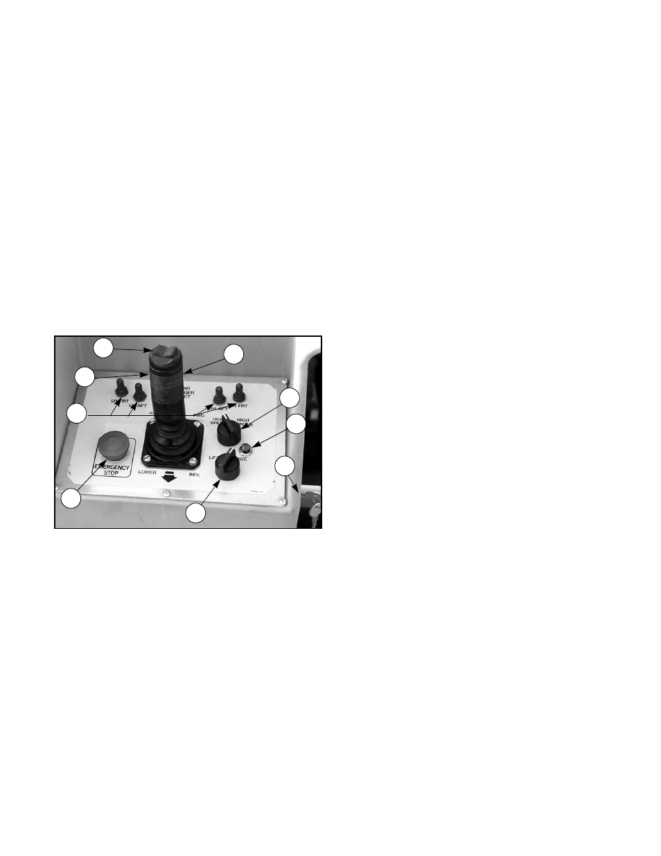
Figure 2: Controller
6. Depress the Interlock switch on the control handle and
position each Outrigger switch to the EXTEND position
to deploy all four Outriggers. Check the Drive Enable
indicator, it should be off.
7. Fully retract all Outriggers and check the Drive Enable
indicator, it should be on.
8. Rehook controller on front guardrail.
9. Turn the platform/chassis switch to CHASSIS.
10. Push the throttle button in. Push chassis raise button
to elevate platform while pushing the tilt sensor off of
level. The platform should only partially elevate and the
tilt alarm should sound. If the platform continues to
elevate and/or there is no alarm STOP and remove the
machine from service until it is repaired.
11. Release the tilt sensor and fully elevate platform.
12. Visually inspect the elevating assembly, lift cylinder,
cables and hoses for damage or erratic operation.
Check for missing or loose parts.
13. Lower the platform partially by pushing in on the chas-
sis lower switch, and check operation of the audible
lowering alarm.
14. Open the chassis emergency lowering valve (Figure 4)
to check for proper operation by pulling and holding the
knob out. Once the platform is fully lowered, close the
valve by releasing the knob.
15. Turn the platform/chassis switch to PLATFORM.
16. Enter the platform making sure the gate is latched.
17. Position drive/lift switch to LIFT.
18. Depress the interlock lever and slowly push the control
lever to UP to raise the platform, fully actuate the con-
trol lever to check proportional lift speed. Slowly pull
control lever to DOWN position to lower platform.
Check that lowering alarm sounds.
19. Depress the interlock lever switch on the control lever
and position any Outrigger switch to the EXTEND posi-
tion, Outriggers should be disabled. If an Outrigger
extends during this test STOP. Lower the platform and
remove the machine from service until it is repaired.
20. Turn controller key switch to OFF, push the emergency
stop button and dismount the platform.
21. Close and secure module covers.
1
2
3
4
9
5
6
7
8
1. Steering Switch
2. Interlock Lever
Switch
3. Control Lever
4. Outrigger Switches
5. Emergency Stop
Switch
6. Drive/Lift Switch
7. Drive Speed/Torque
Selector Switch
8. Drive Enable Indica-
tor
9. Key Switch