Bryant 549B User Manual
Page 6
—
6
—
V. STEP 5 — MAKE ELECTRICAL CONNECTIONS
A. Field Power Supply
All units except 208/230-v units are factory wired for the
voltage shown on the nameplate. If the 208/230-v unit will be
connected to a 208-v power supply, the transformer must be
rewired by moving the black wire from the 230-v
1
/
4
-in. male
spade terminal on the transformer and connecting it to the
200-v
1
/
4
-in. male spade terminal on the transformer.
Refer to the unit label diagram for additional information.
Pigtails are provided for field wire connections. Use factory-
supplied splices or a UL (Underwriters’ Laboratories)
approved copper/aluminum connector.
When installing units, provide a disconnect per NEC.
All field wiring must comply with the NEC and local require-
ments. In Canada, electrical connections must be in accor-
dance with CSA (Canadian Standards Association) C22.1
Canadian Electrical Code Part One.
Install field wiring as follows:
1. Install conduit through the side panel openings. For
units without electric heat, install conduit between
the disconnect and control box.
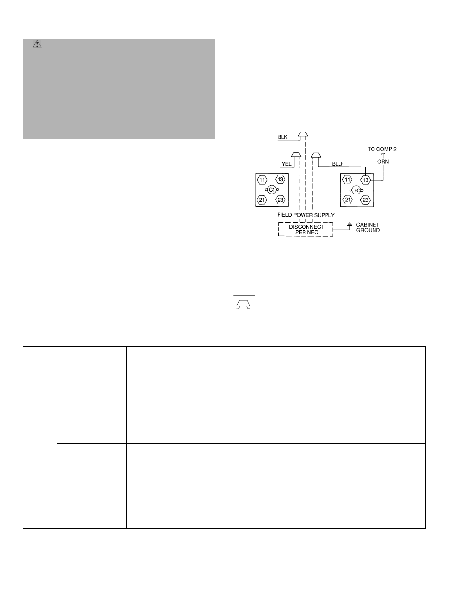
2. Install power lines to terminal connections as shown
in Fig. 6.
3. For units with electric heat, refer to Table 2 and
Accessory Installation Instructions.
NOTE: During operation, voltage to compressor terminals
must be within the range indicated on the unit nameplate
(see Tables 3A-3D). On 3-phase units, voltages between
phases must be balanced within 2%, and the current within
10%. Use the formula shown in Tables 3A-3D, Note 2 on
page 9 to determine the percentage of voltage imbalance.
Operation on improper line voltage or excessive phase imbal-
ance constitutes abuse and may cause damage to electrical
components. (Such operation would invalidate any applica-
ble Bryant warranty.)
Table 2 — Electric Heating Capacities
*Two heater packages required to provide kW indicated.
NOTES:
1. The rated heater voltage is 240 and 480 v. If power distribution voltage varies
from rated heater voltage, heater kW will vary accordingly.
2. To determine heater kW at voltages other than those shown in table, use the
following formula:
Heater kW
new
= Heater kW
rated x
(unit power distribution voltage/rated heater
voltage)
2
As an example:
For a 16 kW heater rated at 240 v with a power distribution voltage of 215 v
kW
new
= 16 kW (215/240)
2
kW
new
= 12.8 kW (rating at 215 v)
WARNING: Unit cabinet must have an uninter-
rupted, unbroken electrical ground to minimize the
possibility of personal injury if an electrical fault
should occur. This ground may consist of electrical wire
connected to unit ground lug in control compartment,
or conduit approved for electrical ground when
installed in accordance with NEC (National Electrical
Code), ANSI/NFPA (American National Standards
Institute/National Fire Protection Association), latest
edition, and local electrical codes. Failure to follow this
warning could result in the installer being liable for
personal injury of others.
UNIT
549B
UNIT VOLTAGE
(60 Hz)
ACCESSORY
kW
ELECTRIC HEATER PART NUMBER
CRHEATER---A00
SINGLE POINT BOX PACKAGE NO.
CRSINGLE---A00
090
208/230/240
(3 phase)
7.8/ 9.6/10.4
12.0/14.7/16.0
18.6/22.8/24.8
24.0/29.4/32.0
31.8/39.0/42.4*
017
010
011
012
012 and 017
007
007
009
009
013
460/480
(3 phase)
12.8/13.9
15.2/16.5
25.6/27.8
30.4/33.0
38.4/41.7*
016
013
014
015
014 and 016
006
006
008
008
—
102
208/230/240
(3 phase)
7.8/ 9.6/10.4
12.0/14.7/16.0
18.6/22.8/24.8
24.0/29.4/32.0
31.8/39.0/42.4*
117
110
111
112
112, 117
012
012
015
015
017
460/480
(3 phase)
12.8/13.9
15.2/16.5
25.6/27.8
30.4/33.0
38.4/41.7*
116
113
114
115
114,116
011
011
014
014
016
120
208/230/240
(3 phase)
7.8/ 9.6/10.4
12.0/14.7/16.0
24.0/29.4/32.0
31.8/39.0/42.4*
37.6/46.2/50.0*
017
010
012
012 and 017
010 and 012
012
012
015
017
017
460/480
(3 phase)
15.2/16.5
25.6/27.8
30.4/33.0
38.4/41.7*
46.2/50.0*
013
014
015
014 and 016
013 and 015
011
014
014
016
016
LEGEND
C
— Contactor
COMP — Compressor
IFC
— Indoor Fan Contactor
NEC
— National Electrical Code
Field Wiring
Factory Wiring
Splice Connection
(Factory-Supplied)
208/230-3-60
460-3-60
Fig. 6 — Power Wiring Connections