Features and controls – Briggs & Stratton 8000 Watt Portable Generator User Manual
Page 11
11
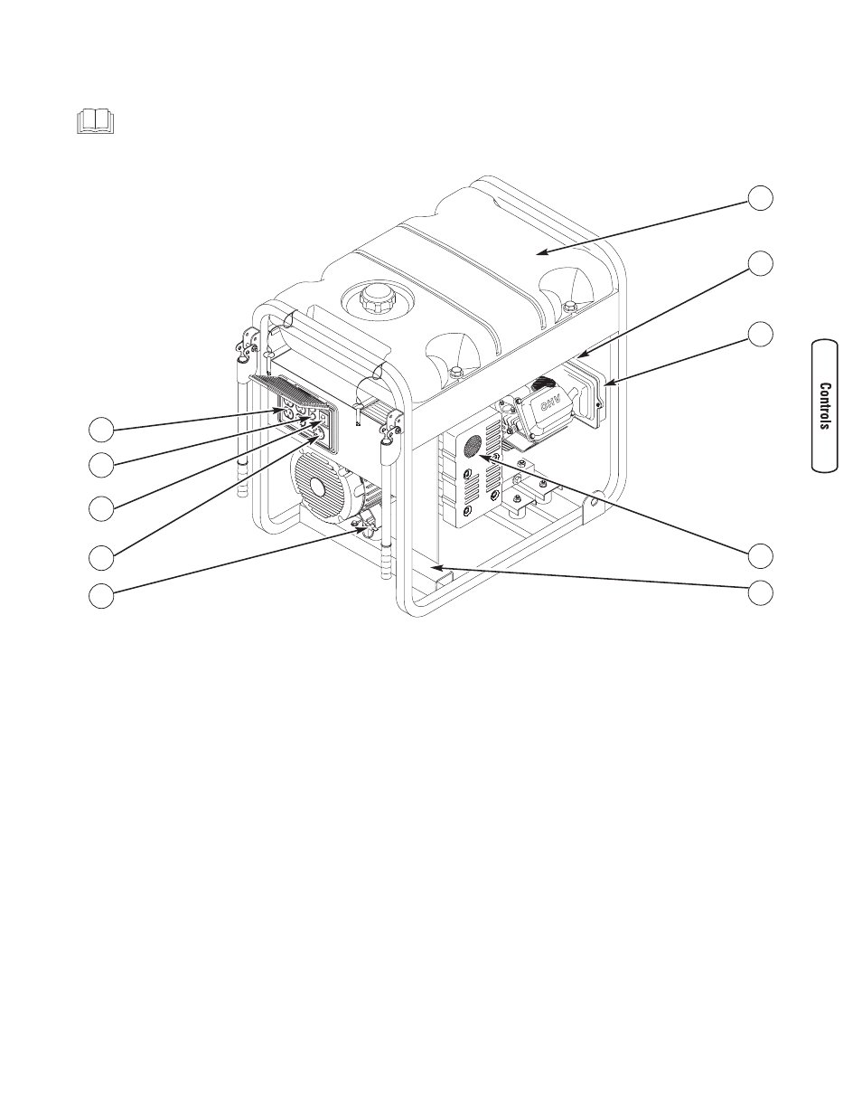
Features and Controls
Read this Operator’s Manual and safety rules before operating your generator.
Compare the illustrations with your generator, to familiarize yourself with the locations of various controls and
adjustments. Save this manual for future reference.
A - 120 Volt AC, 20 Amp, Duplex Receptacles — May be
used to supply electrical power for the operation of
120 Volt AC, 20 Amp, single phase, 60 Hz electrical,
lighting, appliance, tool, and motor loads.
B - Circuit Breakers (AC) — The 120 Volt AC, 20A duplex
receptacles are provided with "push to reset" circuit
breakers to protect the generator against electrical overload.
C - Double Pole Circuit Breaker (AC) — The 120/240 Volt AC,
30A locking receptacle is provided with a double pole
circuit breaker to protect the generator against electrical
overload. This switch also controls all receptacles.
D - 120/240 Volt AC, 30 Amp Locking Receptacle — May
be used to supply electrical power for the operation of
120 and/or 240 Volt AC, 30 Amp, single phase, 60 Hz
electrical, lighting, appliance, tool and motor loads.
E - Grounding Fastener — Consult your local agency having
jurisdiction for grounding requirements in your area.
F - Data Tag — Provides model, revision, and serial number
of generator. Please have these readily available when
calling for assistance.
G - Spark Arrester Muffler — Exhaust muffler lowers engine
noise and is equipped with a spark arrester screen.
H - Air Cleaner — Protects engine by filtering dust and
debris out of intake air.
J - Choke Lever — Used when starting a cold engine.
K - Fuel Tank — Capacity of seven (7) U.S. gallons (26.5 L).
Items Not Shown:
Battery Float Charger Jack — Use battery float charger to
keep the starting battery charged and ready for use.
Engine Identification — Provides model, type and code of
engine. Please have these readily available if calling for
assistance.
Engine Rocker Switch — Set this switch to run position (I)
before using recoil starter. Set switch to stop position (O) to
stop engine.
Fuel Valve — Used to turn fuel supply on and off to engine.
Oil Drain Plug — Drain engine oil here.
Oil Fill Cap /Dipstick — Check and fill engine with oil here.
Recoil Starter — Used to start the engine.
Start Switch — Push and hold in “Start” position for a
maximum of 15 seconds during each start attempt, until
engine starts.
A
B
C
K
F
J
D
H
E
G