Exciter assembly – MBW GPR77 User Manual
Page 15
- 12 -
Exciter Assembly
Refer to Actuator Assembly, page 16.
1.
Press the cylindrical bearings (item #6) into the
exciter housing (item #11).
2.
Install two large retaining rings (item #1) into the
housing.
3.
Press the spherical bearings (item #8) onto the
shafts.
CAUTION
Be sure to press the bearings onto the correct
ends of the shafts! They need to go on the end of
the input shaft (item #25) with the pulley keyway,
and on the end of the idler shaft (item #17) with the
larger hole.
4.
Install two small retaining rings (item #9).
5.
Press the breather pin (item #29) into the cover (item
#12) leaving 3/16” to 1/4” of the pin protruding beyond
the inside of the cover, and replace the felt filter (item
#2) and the retaining ring (item #3).
6.
Press the input shaft (item #25) into the cover by
pressing on the bearing outer race only, and install
the large snap ring (item #1).
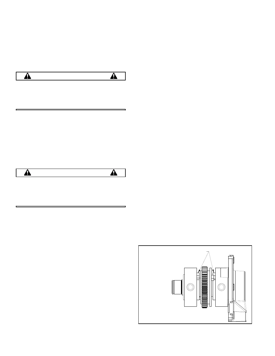
CAUTION
Apply high strength thread locker to the threads
in the shaft only! Correct weight placement is
CRITICAL! Refer to the figures on page 12 and
page 20 to ensure proper orientation and place-
ment.
7.
Bolt the lower weight (item #14) to the input shaft
using capscrew (item #10) by applying high
strength thread locker to the threads in the shaft
only, torque to 100 ft./lb.!
8.
Install key (item #4) to the input shaft using medium
strength loctite.
9.
Press on gear (item #15) with the timing mark up
using medium strength loctite.
10. Repeat step #7 for the upper weight (item #14).
11. Repeat step #6 for the idler shaft (item #17).
12. Bolt the lower weight (item #20) to the idler shaft
using capscrew (item #10) by applying high
strength thread locker to the threads in the shaft
only, torque to 100 ft./lb.!
13. Press the slide bushing (item #18) centered into the
gear (item #16).
14. Lightly oil the idler shaft and slide on the gear with the
timing mark up.
15. Repeat step #12 for the upper weight (item #19).
16. Support the shafts by the weights and press on the
inner races of the cylindrical bearings (item #6).
17. Install two small retaining rings (item #9).
18. Bolt the shifter assembly (item #24) to the cover using
flanged capscrew (item #33) and medium strength
loctite applied to only the screw threads.
19. Align the timing marks on the gears and hold all
shafts vertical.
20. Set the new gasket (item #13) on the cover.
21. Place the housing on top of the cover being sure to
smoothly insert the shafts into the housing.
22. Carefully turn over the entire exciter so the cover is
facing up.
23. Bolt the cover to the housing using flanged
capscrews (items #34).
24. Reassemble all bearing access hole capscrews (item
#30) and brass washers (item #35) using liquid
gasket maker sealant.
25. Lightly lubricate the sealing lip of the new oil seal
(item #7) and press it into the cover.
26. Install the stone guard (item #27) on the cover using
flanged capscrew (item #31) and apply thread
sealant to the threads.
27. Install the key (item #4 or #28) and the pulley (item
#26) using the washer (item #23) and bolt (item #32)
to secure them to the input shaft. Use medium
strength loctite on the capscrew threads.
28. Bolt the actuator assembly (item #22) to the exciter
housing using capscrews (item #31).
29. Add oil to the exciter per the fluid level chart on page
6 and install the pipe plug (item #36) (see Exciter Oil
Change Procedure, page 6).
30. Reassemble the bottom plate, roll cage, engine and
shifter cable by referring to the disassembly
instructions on page 9.
31. Check the shifter cable assembly for proper
adjustment (see Checking the Shifter Cable, page 7).
SHIFTING DOGS ORIENTED
ON TOP AND FACING IN.
Figure 2: Correct weight Orientation