PHCC Pro Series Pro Series C33 User Manual
Page 13
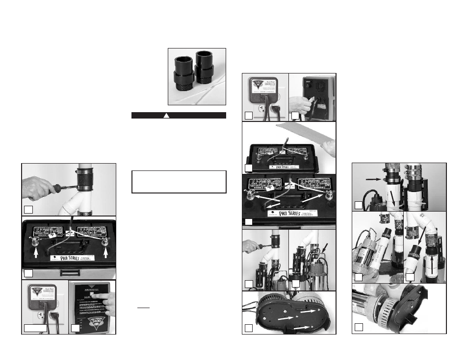
18. Ease the Y-assembly back into the rubber
union on the discharge pipe and tighten the
hose clamps.
19. Connect the backup pump to the back of the
gray control unit.
20. Insert the fluid sensor into the top of the
battery, or into the battery cap, depending
on which battery you own.
21. Connect the battery wires to the battery
terminals, WHITE to the NEGATIVE (-) post,
and BLACK to the POSITIVE (+) post.
22. Plug the power cord from the gray control
unit into the outlet. You should provide
additional protection for the system by using
a surge protector.
23. Plug the primary pump into the blue
controller, and plug both into the wall outlet.
24. If any of the alarms are sounding, press the
GRAY button for 1 second.
REPLACING THE PRIMARY PUMP
Before you begin this process, you will need a
new AC pump, new check valves, and new wire
ties. The check
valves have a
1½” MPT on
one end, and a
1½” SLIP on
the other end.
See page 15 for
part numbers.
Risk of electrical shock or battery explosion,
which can cause serious injury or death. Wear
eye protection. Work in a well-ventilated
area. DO NOT smoke or allow a spark or flame
in the vicinity of the battery. Avoid dropping
metal tools on the battery. Review the safety
instructions on page 1.
1. Unplug the primary pump, the blue controller,
and the power cord for the backup control
unit from the wall outlet.
2. Unplug the backup pump from the back of the
gray control unit.
3. Remove the cover of the battery box and fan
the area around the top of the battery with a
piece of cardboard (or another non-metallic
material) to remove any hydrogen or oxygen
gas that may have been emitted from the
battery.
4. Remove the sensor from the battery; remove
the battery wires from the battery terminals.
Be sure they DO NOT touch each other while
one is connected to the battery.
5. Slowly loosen the rubber union on the top of
the combination pump assembly to separate
the pipes. The water trapped in the pipe will
pour out into the sump as the rubber union is
loosened.
6. Lift the pump assembly out of the pit by the
handle on the primary pump. Tip the
assembly over the sump pit to drain any
remaining water.
7. Lay the pumps down and remove the three (3)
screws holding the primary pump to the
“sump foot”. The strainer on the primary
pump will separate from the pump when the
screws are removed. SAVE THESE SCREWS or
replace them with #10-24 x 1½” stainless
steel screws.
8. Loosen the hose clamp holding the float
switch, cut the wire tie holding the switch,
and remove the switch from the pipe. Note its
position.
9. Loosen the hose clamps on the no-hub
connector on top of the primary pump and
ease the pump out of the connector.
10. While you have the pump apart, this would
be a good time to replace the check valves.
A check valve with 1½”MPT on one end, and
1½” SLIP on the other is commonly
available, or you may order this part
#1141003 from Glentronics.
11. Remove the screws from the strainer on the
new primary pump and discard them before
you place it on the “sump foot”. You will
Page 12
18
22 & 23
24
POSITIVE
POST
NEGATIVE
POST
21
!
DANGER
YOU WILL BE DISCONNECTING ALL THE
WIRES. BE SURE THEY DO NOT FALL INTO THE
SUMP PIT.
9
10
11
4
REMOVE
5
6
7
1
2
3
LIFT
8