Thermocouple wire harness – J.P. Instruments EDM 730 Instrument Installation Manual User Manual
Page 10
FAA APPROVED INSTALLATION MANUAL FOR THE EGT-701 Report 103
INSTALLING THE EGT-701 SCANNER® 1/20/09
Rev-E Page 10 of 30
Before you begin, note that the most common cause of probe problems is poor
terminal crimps.
When cutting each pair of leads in the wiring harness to the proper length to connect to the probes, leave enough
slack in the harness so that probes from adjacent cylinders may be interchanged if necessary for trouble-shooting and
servicing. Thermocouple wire length is not critical and should be trimmed to any length as required for a clean
installation.
The Temperature probes must be wired with the correct polarity. Each wire is marked with the cylinder number. The
EGT and CHT probes connect to the temperature indicator with yellow jacket Teflon Chromel Alumel wire supplied.
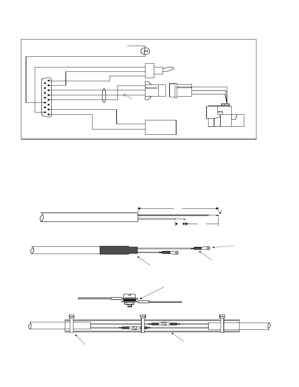
Strip the wires as shown below, observing color codes.
Important: fold back the wire double before
crimping terminals.
1/4"
1 1/2"
Fold back wire
double before
crimping terminals
2 1/4"
Thermocouple wire harness
red
yellow
Terminate each wire with a crimp-on ring terminal, provided. The ring terminals may be crimped with a “service-type”
tool, however AMP part number 48518 crimp tool is recommended. Verify the quality of each crimp with a sharp tug on
the wire. The terminal should be impossible to pull off when crimped correctly.
shrink tubing
shrink tubing
ring terminal
Place a ¼ x 4 inch sleeve over each pair of wires in the harness. Connect the harness ring terminal to the probe ring
terminal using the supplied number 4 screws and nuts, placing the star washer between the ring terminals, not against
the nut.
Important: place star waster between two ring
terminals and tighten nut and bolt as
necessary
to instrument
to probe
Slide the sleeve over the joint and secure with three tie-wraps.
1/4 x 4" sleeve
tie-wrap 3 places
Cut red lead if
transducer is
also connected
to another fuel
flow instrument
IN
OUT
WHT
BLK
RED
WHT
BLK
RED
fuel flow option
connector
1
1
9
8
15
FF
COM
EGT
+12/24 avionic bus
GPS
RS-232 input to EDM-700
GPS output
GPS input
(some KLN series only)
RS-232
output from
EDM-700
8
7
6
5
4
3
2
1
Fuel Flow Transducer
FloScan 201 -A, -B, -C, or 231
Alarm lamp or enunciator
(customer supplied option)
11
9
panel
mounted
switch
(alarm wire not supplied)
EGT
ALL
FF