Valley panel and trim installation – Mueller Corrugated Panel User Manual
Page 16
16
Details are subject to change without prior notice.
16
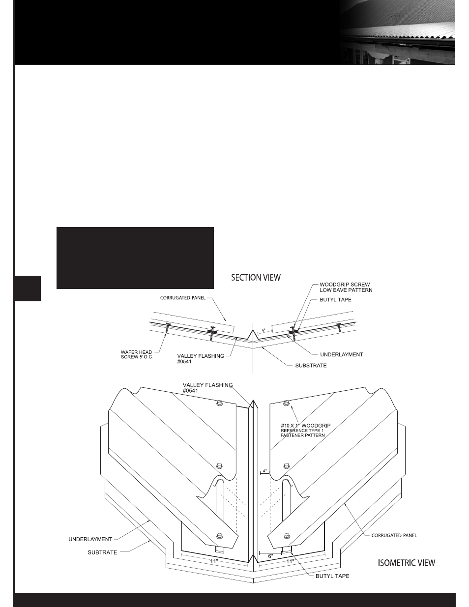
VALLEY PANEL AND TRIM INSTALLATION
Details are subject to change without prior notice.
1. Start at the low end, trim and place the valley flashing. The valley end should overhang the eave trim 1”.
2. If there is an end lap required in the valley pieces, caulk and lap at least 8”.
3. Use wafer head screws on 5’ centers to secure the valley in place along the outside edge.
4. Hem the edges of the valley over the eave trim, after trimming the center “V” back 1” to align with the edge of
the eave. Leave a tab to bend and cover the exposed opening of the center “V”.
5. Place butyl tape on the upper surface of the valley 6” up slope from the “V” of the valley trim, before applying
intersecting panels.
6. Field cut the panels that intersect the valley holding the end of the panel 4” back from the “V” of the valley trim
and parallel to the “V” of the valley.
7. Attach panel at valley using eave screw requirements for panel being installed.
NOTE: Alternate trim profiles are acceptable using the screw pattern shown.
NOTE: To comply with Texas Windstorm
Certification Testing, #12x11 SDT Type
A screws must be used in place of the #9
Woodgrip screws.