Rubicon Express RE7500 SERIES User Manual
Page 7
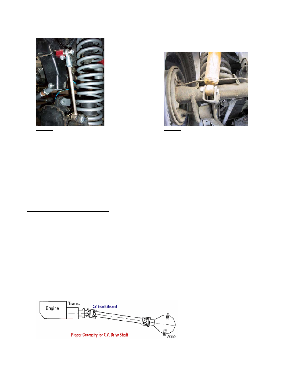
E. Install front sway bar quick disconnects per instructions supplied with disconnects – refer to Photo 16. The latest adapter bracket
should mount down over the top of the sway bar and bolt should go up through sway bar, then through adapter bracket. The
carriage bolt head should be toward the frame at top end of disconnects. Use the thick round spacer between the bottom
disconnect and mount and put the nut on the tire side of the mount. Install disconnect tubes and snap pins.
Photo 16
Photo 17
Step 8 – Shocks and brake lines
A. Install longer front shocks. Some require bar pins to be installed through the bottom shock eyes (use light grease).
B. Position and weld on rear shock mounts – refer to Photo 17 for typical installation. The slot in the bracket is provided to place
over control arm bracket, but different shocks or lengths may require different positions. Generally, the mounts end up in the
neighborhood of 45 degrees, but it’s better to check that there is about 1” of shock travel remaining when the bump stops are
touching their pads. Install longer rear shocks.
C. Fully remove front factory brake hoses and replace with the supplied stainless steel ones. Some require positioning the block and
line vertically at the caliper. Watch line routing so they do not catch on anything during axle articulation. Use angle brackets and
e-clips at the body end.
D. Fully remove rear brake line and install new one. Watch the routing so it does not catch on anything during axle articulation.
Step 9 - Final details and adjustments
A. Install wheels and lower vehicle.
B. Adjust the track bars to fit into the mounts with the axles as centered as possible (centering is not hyper critical).
C. Thoroughly bleed brake lines per factory manual and check for leaks and a firm pedal.
D. Torque all bolts to factory specs and double-check your work.
E. Test drive and note location of steering wheel and any driveline vibrations.
F. Adjust drag link to center steering wheel and align vehicle as soon as practical. Minimum factory caster and maximum factory toe-
in seems to work well with these front ends (see Troubleshooting as well).
G. Adjust control arms if necessary. Note: Due to vehicle variations installer must verify proper driveline angles and axle placement
to avoid tire rubbing or axle coming in contact with gas tank, steering linkage, or exhaust system. Shown below is picture
showing proper pinion angle for a CV style drive shaft (see Troubleshooting as well).
H. Retighten all bolts after 50 miles and again after every off road excursion.
RE7500A Page 7 of 8