Rubicon Express RE7500 SERIES User Manual
Page 4
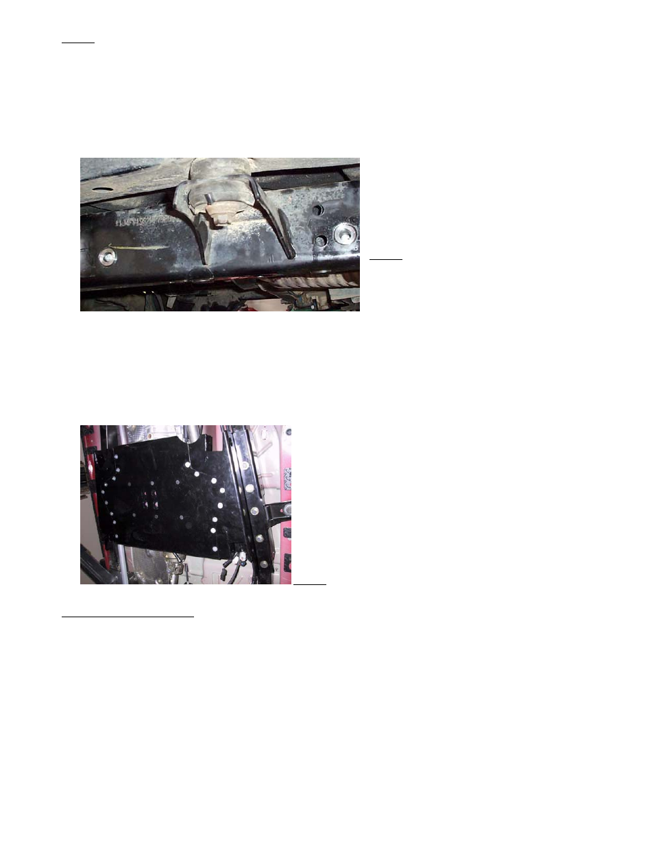
Photo 6
K. Install six frame spacers into the holes you just drilled. We recommend welding the outside surface of spacer to the frame. If
welding, chamfered edge goes to outside of frame for weld fillet. Grind flush when finished. If not welding, chamfer goes inward.
Use ½” rod or bolt to align spacer with ½” hole in inside surface frame rail – refer to Photo 7. Repeat welding and grinding at the
remaining five spacers and paint all bare metal to protect it.
Photo 7
L. You are now ready to permanently install pan. A total of 10 bolts will be used through bottom of frame braces and crossmember,
and a total of 6 bolts will be used through side of frame braces and frame rails – refer to Photo 8. Install all remaining flat head
bolts at center section and bolt the transmission mounting plate to crossmember and factory transmission mount.
Once the pan is installed, you can attach the control arm support braces to the frame (97-02) or back to the belly pan (03+). Run
a bolt through the hole in the control arm bracket for alignment, then mark and drill the holes in the frame (97-02) or the belly
pan (03+). Refer to photo XXX & XXX.
Photo 8
Step 3 – Front control arms
A.
FRONT - Adjust front lower control arms’ length to an initial setting of 37.5” from bolt center to bolt center. Final arm lengths
seem to vary from around 37.5” to 38” depending on lift, axle squareness (see step C) and differential clearance to track bar.
Install adjustable end of arm to front crossmember with supplied hardware (zerk on top). Position the arms so the welded on
brackets for the front upper arms are on top and leaning toward each other.
B.
Adjust front upper control arms’ length to an initial setting of 15-7/8” from bolt center to bolt center. Install front upper arms’
rubber bushing end into the welded on bracket of the lower arms with supplied hardware. The upper arms will be used to adjust
final caster and pinion angle.
C.
Attach front lower control arms to axle with factory hardware, and attach upper arms to axle with supplied hardware – refer to
Photo 9. Checking distance from axle mount to front factory crossmember bolt should verify if axle is square, adjust if necessary.
RE7500A Page 4 of 8