Rubicon Express RE7500 SERIES User Manual
Page 6
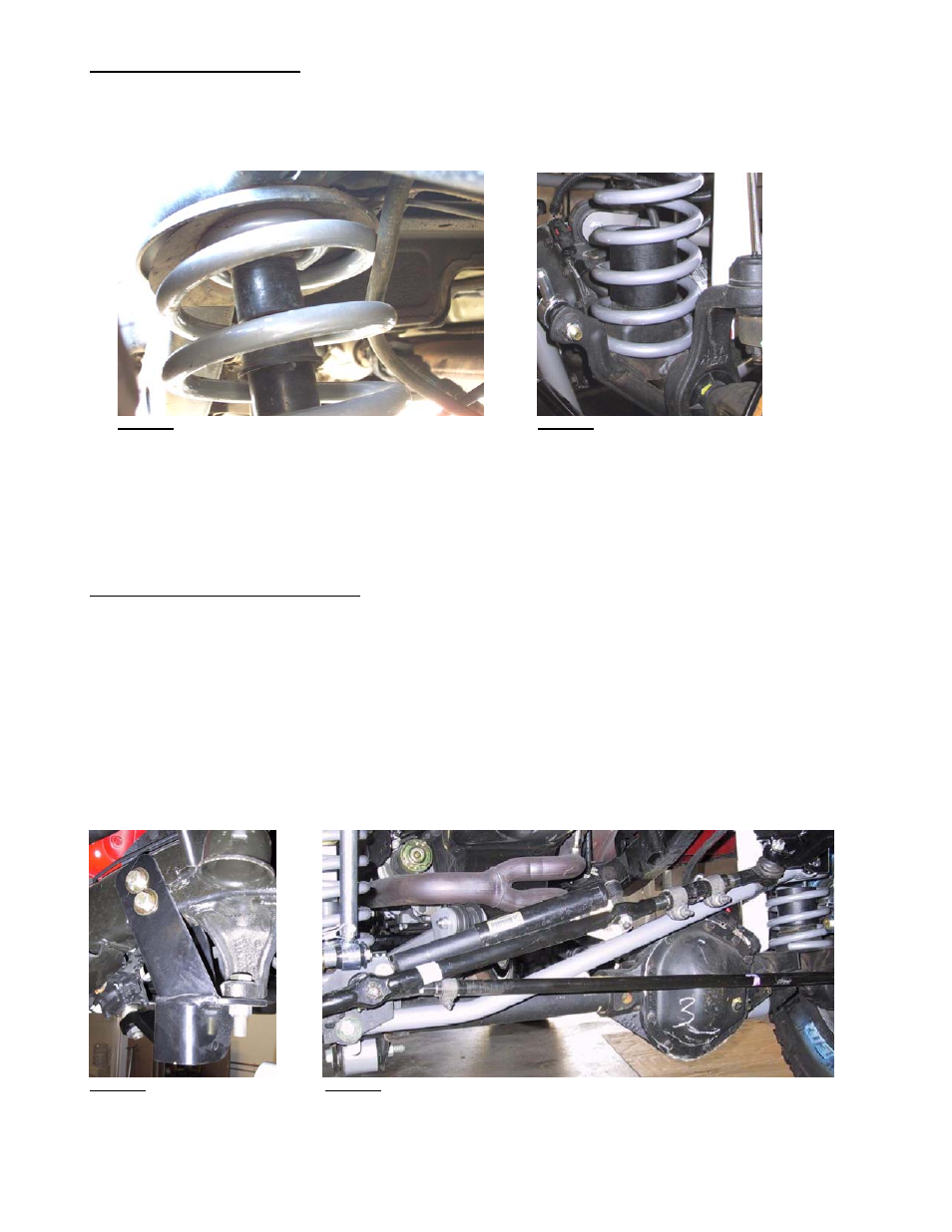
Step 6 – Bump stops and coils
A. REAR BUMP STOPS - Remove the rubber insert from the rear bump stop. Remove the bump stop cup. Place the spacer between
the bump stop cup and the tower using the supplied longer metric hardware. Reinstall stock rubber bump stop on 3.5” and 4.5”
kits, or install RE1395 extended bump stops on 5.5” kits - refer to Photo 11.
B. REAR COILS - Install rear coils.
Photo 11
Photo 12
C. FRONT BUMP STOPS - Drill 5/16” hole in center of lower spring pads. Use self-tapping bolt through bump stop to cut threads in
lower spring pad. Remove bolt and spacer, it will be installed with the spring.
D. FRONT COILS - Install the front coils with the bump stop inside of the coil – refer to Photo 12. Coil spring compressors may be
useful. Once the spring is in place, put the bolt through the bump stop extension and thread the bolt into the lower spring pad
(careful these strip easily). Be sure to rotate the coil to index the spring with lower coil cup, and reinstall coil spring clamp if
removed earlier (not all vehicles have the spring clamps).
Step 7 – Track bars and sway bar links
A. FRONT TRACK BAR/BRACKET – drill out factory bracket to 5/8” with a high quality bit and some cutting fluid (or similar). If using
the RE1600 track bar skip to step ‘D’. If installing the RE1611 drop bracket for the RE1610 track bar, attach drop bracket with
supplied 5/8” hardware to the factory one so the new bracket slides up each side of the frame rail. Drill ½” holes through the
frame at the two holes in the new bracket being sure holes are perpendicular to the frame. Attach new bracket to the frame with
supplied ½” hardware - Refer to Photo 14.
B. FRONT TRACK BAR - Attach new track bar to lower mounting bracket (axle side) using factory hardware. This will be the poly-
bushing end of bar. Position bar so it starts out parallel with the axle (horizontal), then turns up toward the frame bracket. Before
connecting bar to upper mount, center the vehicle over the axle by measuring the distance from front fender flare to tire on both
driver and passenger sides of the vehicle, then adjusting vehicle until body is centered over the axle. The easiest way to
accomplish this is when the vehicle is back on its wheels, have an assistant turn steering wheel left or right as necessary. Adjust
spherical bearing end so that it will fit directly into the upper mount with the body centered. Tighten the jam nut to prevent the
spherical bearing end from moving on the threads. Use supplied 10mm hardware to attach RE1610 to new bracket, or supplied
5/8” hardware to attach RE1600 bar to factory mount – refer to Photo 15 for typical installation.
Photo 14
Photo 15
C. If using the RE1611 dropped track bar bracket, install the drop pitman arm. Use a good pitman arm puller to remove old one
D. Install rear sway bar links just like the factory ones.
RE7500A Page 6 of 8