Testing the manual reset high limit switches, Burner orifice and gas control valve – L.B. White 350 Premier Dual Fuel User Manual
Page 19
This heater has two limit switches. One is located at the
burner end of the heater. The other is located on the fan
housing at the motor end of the heater. Both high limit
switches should be tested a minimum of once per year
when the heater is given a thorough cleaning.
1. Remove the high limit switches.
2. Holding the switch by one of its mounting legs, apply
a small flame only to the sensing portion on the back
of the switch. Be ccareful nnot tto m
melt tthe pplastic
housing oof tthe sswitch w
when cconducting tthis ttest.
3. Within a minute, you should hear a pop coming from
the switch, which indicates the contacts of the switch
have opened.
4. Allow the switch to cool for about a minute before
firmly pressing its reset button. The switch may have
a red cap over the button. If you removed the cap to
reset the switch, ensure you put it back on.
5. Check for electrical continuity across the switch
terminals to make sure the contacts have closed.
FIG. 23
RESET BUTTON
SENSING
SURFACE
TERMINAL
FLAME
MOUNTING
LEG
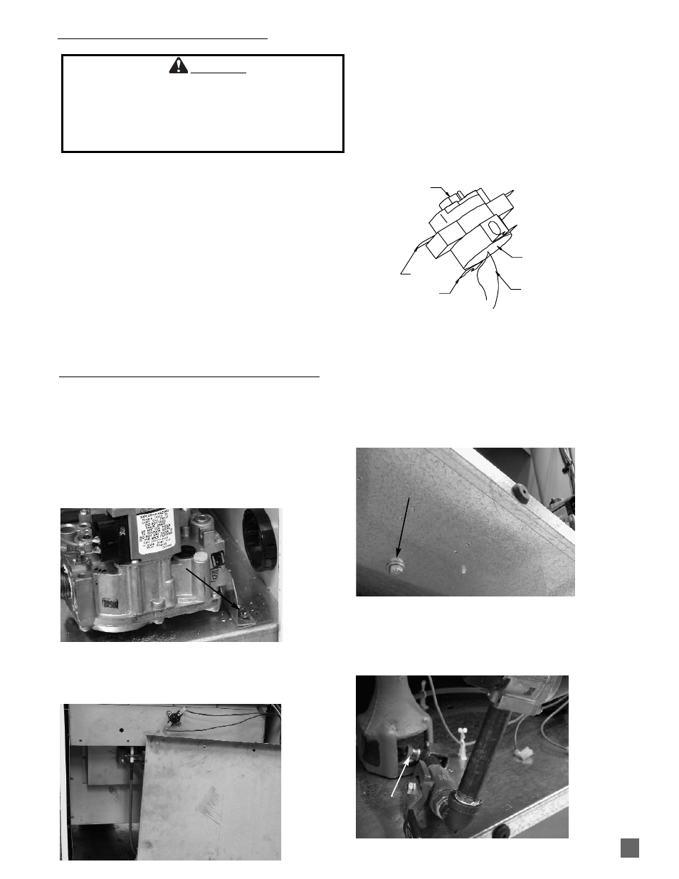
1. Remove hose and pipe nipple from control valve inlet.
2. Open burner end door.
3. Remove screws from gas control bracket and
disconnect control valve’s electrical wiring. See Fig.
24.
FIG. 24
4. Remove burner panel. See Fig. 25.
FIG. 25
5. Remove burner retaining bolt from under base at gas
control end of heater. See Fig. 26.
FIG. 26
6. Lift and pivot the gas train assembly so orifice is
exposed. See Fig. 27. Remove control valve or orifice
as needed.
FIG. 27
SCREW
BOLT
TESTING THE MANUAL RESET HIGH LIMIT SWITCHES
WARNING
Fire H
Hazard
■
Do not operate the heater with the high limit switch
bypassed.
■
Operating the heater bypassed high limit switch may
lead to overheating, possibly resulting in a fire, with
subsequent damage to the heater or property damage.
ORIFICE
19
BURNER ORIFICE AND GAS CONTROL VALVE