Steele Products SP-PB113 User Manual
Page 5
17
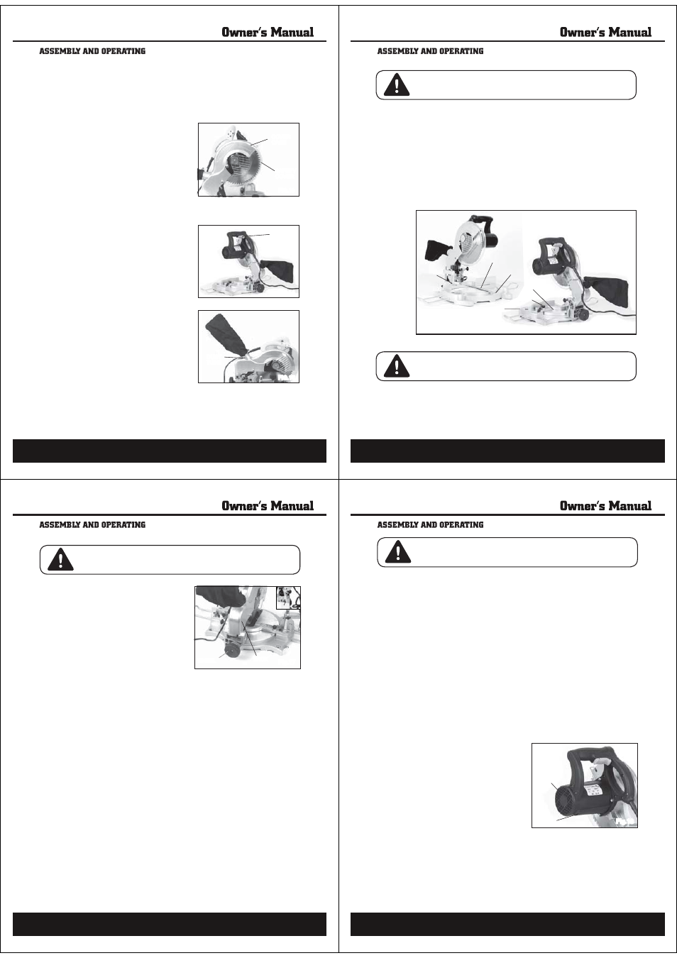
TO SAFETY COVER
1. The transparent Safety Cover automatically rotates to cover the Saw Blade
when the Cover Case is lifted. When the Cover Case is lowered, the Safety
Cover rotates back out of the way. (See Figure 13)
2. Do not disconnect or remove the Safety Cover. Do not operate the Miter Saw
if the Safety Cover is damaged or missing. (See Figure 13)
3. If the transparent Safety Cover becomes so dirty that the Saw Blade cannot
be seen clearly, disconnect the elec-
trical Power Cord from its electrical
outlet and clean the Safety Cover with
a soft, damp, cloth. A mild detergent
may be used, but do not use solvents
which may damage the Safety Cover.
(See Figure 13.)
THE POWER SWITCH
1. Before plugging in the Miter Saw,
check the operation of the Power
Switch. Do not operate the Miter Saw
if the Power Switch is not operating
properly. To turn on the Miter Saw,
simply squeeze the Power Switch. To
turn off the tool, release pressure on
the Power Switch. (See Figure 14.)
THE DUST BAG
1. The Dust Bag catches and holds the
wood chips and saw dust when the
Miter Saw is in operation. (See Figure
15)
2. The outside diameter of the Dust Tube
is 1-3/4” to which the Dust Bag or a
vacuum hose (not included) may be
attached. It is recommended that only
CSWCNKſGFVGEJPKEKCPRGTform this
procedure. (See Figure 15)
FIG.13
COVER
CASE
SAFETY
COVER
FIG.14
POWER
SWITCH
FIG.15
DUST
TUBE
18
TO ADJUST THE CUTTING DEPTH
1. The depth of cut may be adjusted to a maximum of 5-1/3” at 90, and 3-3/4”
at 45°.
2. Slightly loosen the Screw and pull the Miter Saw’s Cover Case down- ward
as far as it will go. Observe whether the edge of the Saw Blade passes com-
pletely through the Kerf Board. (See Figure 16)
3. If the Saw Blade does not pass completely through the Kerf Board, lower the
Saw Blade further by loosening the Screw. (See Figure 16)
4. After adjusting the Screw, press down on the Miter Saw and make sure the
Saw Blade does not contact the bottom of the Table or any other part of the
Saw Base. (See Figure 16)
5. If the Saw Blade touches the Table or any other part of the Saw Base, tighten
the Screw to raise the Saw Blade slightly until it clears. (See Figure 16)
WARNING! Prior to performing this procedure, make sure the Power Cord of
the Miter Saw is unplugged from its electrical outlet.
Fig.16
TO ADJUST THE MITER ANGLE
1. The miter angle of a cut may be adjusted 0 - 45 degrees to the right or left.
To do so, turn the Angle Lock located at the back board. (See Figure 16)
2. While the Angle Lock is turned on, move the Handle to the right or left
until the desired miter angle of cut is indicated by the Gauge located on
the Base.Then, screw down the Angle Lock to lock the Miter Saw in place.
(See Figure 16)
WARNING! Prior to performing this procedure, make sure the Power Cord of
the Miter Saw is unplugged from its electrical outlet.
GAUGE
TABLE
KERF BOARD
BASE
ANGLE LOCK
ANGLE LOCK
19
TO ADJUST THE BEVEL OF CUT
1. The bevel angle (or Saw Blade tilt
capacity) may be adjusted from
0 - 45 to the left. To do so, loosen
the wheel located at the rear
of the Miter Saw. (See Figure 17)
2. Tilt the Back Rack until the
desired bevel angle of cut is
achieved as indicated on the
Gauge. Then, re-tighten the
Wheel to lock the Back Rack in
place. (See Figure 17)
WARNING! Prior to performing this procedure, make sure the Power Cord
(102) of the Miter Saw is unplugged from its electrical outlet.
Fig.17
BASIC OPERATION
1. Make sure the Power Cord of the Miter Saw is unplugged from its electrical
outlet. Then, if necessary, make adjustments to the workpiece Holder, cutting
depth, miter angle, and bevel angle.
2. Raise the Saw Blade up to allow positioning of the workpiece.
3. Check to make sure the Power Switch is operating properly.
4. Place the workpiece on the Table and against the Guide Fence.
5. Use the Clamp Assembly to hold the workpiece in place.
6. Plug the Power Cord into the nearest 120 volt, grounded, electrical outlet.
7. Squeeze the Power Switch to turn on the Miter Saw.
8. When the Saw Blade is turning at full speed, slowly bring down the Motor
Housing to complete the cut. NOTE: Feed the Saw Blade into the workpiece
gradually. Do not force the machine to remove material faster than it was
designed to cut.
9. When cutting a large workpiece, make sure its entire length is properly sup-
ported. If necessary, use a roller stand (not included) with a larger workpiece.
10. Never attempt to remove material stuck in the moving parts of the Miter Saw
while it is plugged in and running.
11. Turn off the Miter Saw if the workpiece is to be backed out of an uncom-
pleted cut.
12. When the cut is complete, release the Power Switch to turn off the Miter Saw.
13. Wait until the Saw Blade comes to a complete stop. Raise the Motor Hous-
ing. Then, unplug the Power Cord from its electrical outlet.
14. Loosen the Clamp Assembly, and remove the workpiece and scrap material
from the Table.
WHEEL
BACK RACK
GAUGE
20
WARNING! Always make sure the Power Switch (98) is in its “OFF” position,
and unplug the Power Cord from its 120 volt electrical outlet before performing
any inspection, adjustments, maintenance, or cleaning.
1. Make sure the power tool is cool to the touch before inspection, mainte-
nance, and cleaning begin. Always protect your hands by wearing work
gloves.
2. Before each use, inspect the general condition of the Miter Saw. Check for
loose screws, misalignment or binding of moving parts, cracked or broken
parts, damaged electrical wiring, loose, cracked, or bent Saw Blade, and
any other condition that may affect its safe operation. If abnormal noise or
vibration occurs, have the problem corrected before further use. Do not use
damaged equipment. Never work with a dull saw blade.
3. Daily: With a soft brush, cloth, or vacuum, remove all dust and debris from
the Miter Saw. Then, use a premium quality, lightweight machine oil to lubri-
cate all moving parts except the Saw Blade.
4. To replace the Motor Carbon Brushes: It may become necessary at some-
time to replace the two Carbon Brushes when the Motor performance
de- creases, or stops working completely. The Carbon Brushes are located
on each side of the Motor Housing. To do so, remove the two Brush Covers.
Then, remove the two Carbon Brushes from the Brush Holders. If the Carbon
Brushes are worn down more than 1/2, replace both Carbon Brushes. If,
however, the Carbon Brushes are just dirty they may be cleaned by rubbing
them with a pencil eraser. When installing the Carbon Brushes, make sure
the carbon portion of the Carbon Brushes contact the Motor Armature, and
that the springs face away from the
Motor. Also, make sure the springs
operate freely. After cleaning or re-
placement, replace the Brush Hold-
ers. NOTE: New Carbon Brushes
tend to arc or spar
NZKHQÀUVWXVHG
until they wear and conform to the
Motor’s Armature. (See Figure 18)
5. NOTE: With the exceptions of
Steps #1, #2, #3, and #4 all other
maintenance and servicing should
be performed only b
\DTXDOLÀHG
service technician.
Fig.18
CARBON
BRUSH
CARBON
BRUSH
(NOT SHOWN)