Steele Products SP-PB113 User Manual
Page 4
Rating ..................................................................... 120 V, 60 Hz, AC Only, 15 A
No Load Speed .................................................................................. 4500 /min.
Blade Diameter ............................................................................. 10” (254 mm)
Blade Arbor .................................................................................... 1” (25.4 mm)
Cutting Capacity 90
º x 90º .................................................... 2-15/16” x 5-1/3”
90
º x 45º...................................................... 2-15/16” x 3-3/4”
45
º x 90º.......................................................... 1-1/3” x 5-1/3”
45
º x 45º.......................................................... 1-1/3” x 3-3/4”
Net weight ............................................................................................. 24.2 lbs
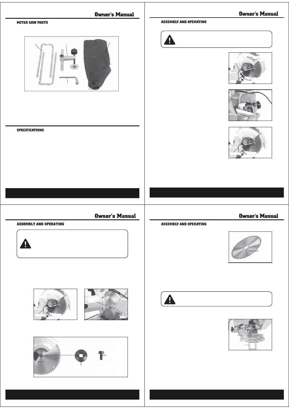
Fig. 4 illustrates all the loose parts packed with the saw.
13
1
2
3
4
Key No.
Description
Qty
1
Extension Bar
2
2
Work Clamp
1
3
Dust Bag
1
4
Socket Wrench
1
14
SAFETY RULES
1. When replacing the Saw Blade,
make sure the new Saw Blade has a
diameter of 10”, an RPM rating of
at least 7000, and an arbor hole of
1” diameter.
2. DOWN When installing a Saw Blade,
make sure the teeth of the Saw Blade
point downward, and that the direc-
tion of the arrow shown on the Saw
Blade matches the direction of the
arrow shown on the Cover Case. (See
Figure 5.)
3. Lock the Saw Blade in its upward
position. To do so, pull out on the
Cross Pin. Raise and hold the Cover
Case of the Miter Saw fully upward.
Turn the Cross Pin 90 degrees. Then,
insert the Cross Pin into the deep slot
in its locked position. (See Figures 6
and 7)
WARNING! Prior to performing any assembly and/or adjustment procedures,
make sure the Power Cord of the Miter Saw is unplugged from its electrical
outlet. Make sure the unit has completely cooled, and wear heavy-duty work
gloves.
COVER CASE
ARROW
SAW TEETH
POINTING DOWN
SAW BLADE
ARROW
FIG.5
FIG.6
PIN
SCREW
SAFETY
COVER
LARGER
COVER
WRENCH
BOLT
FIG.7
15
CAUTION! The Cross Pin should always be activated in the “locked
down” position when the Saw is not being used and when the Saw is
being transported. The Cross Pin should be activated in the “locked up”
position only when changing Saw Blades. NEVER use the Cross Pin in
any cutting operation. The Cross Pin allows the operator to lock the Saw
Blade in position, preventing the Saw Blade from being raised or lowered. (See
Figures 6 and 7.)
4. Loosen the Screw that holds the Large Cover in place. Then, use the Wrench
to remove the Bolt. (See Figure 8.)
5. Rotate the Large Cover and Safety Cover up and out of the way. (See Figure
8.)
6. Depress the Spindle Lock to keep the Saw Blade from turning. (See Figure
9.)
7. Use the Wrench to unscrew and remove the Spindle Bolt. NOTE: The
Spindle Bolt unscrews in a clockwise direction. Then, remove the Outer
Flange. (See Figure 10.)
SCREW
SAFETY
COVER
LARGER
COVER
WRENCH
BOLT
FIG.8
FIG.10
FIG.9
SPINDLE
LOCK
OUTER FLANGE
COUNTERCLOCKWISE
TO TIGHTEN
SPINDLE BOLT
CLOCKWISE
TO LOOSE
16
8. Release pressure on the Spindle Lock.
(See Figure 9.)
9. Wearing heavy duty work gloves to
avoid accidental cuts, remove the old
Saw Blade. (See Figure 11)
10. Install the new Saw Blade, make
sure the teeth of the Saw Blade
are pointing downward. (See Figure
5)
11. Reassemble the Outer Flange, and
5RKPFNG$QNVſrmly. (See Figure 10)
12. Swing the Large Cover and Safety Cover back in place, make sure the
Safety Cover covers the Saw Blade. (See Figure 8)
13. Reinstall the Bolt, and retighten the Screw. (See Figure 8)
14 . Make sure the Safety Cover returns to its original position prior to operating
the Miter Saw.
CAUTION! Make sure to pull out on the Cross Pin. Turn the Cross Pin 90 de-
grees. Then, insert the Cross Pin into the shallow slot in its unlocked position.
NEVER use the Cross Pin in any cutting operation. (See Figure 6.)
TO ASSEMBLE ADDITIONAL ACCESSORIES
1. A workpiece Clamp Assembly can
be installed by inserting the As-
sembly into the hole located in the
Guide Fence. Once inserted, lock the
Assembly in place with the Thumb
Screw. To clamp the workpiece to the
Base of the Miter Saw, turn the Ad-
justing Knob on the Clamp Assembly
clockwise. (See Figure 12.)
2. A workpiece Holder can be inserted
into each side of the Base, adjusted
for the desired length. The Holders should be used as supports when cutting
longer length workpieces. (See Figure 12.)
FIG.12
CLAMP
ASSEMBLY
BASE
HOLDER
GUIDE
FENCE
FIG.11
SAW
BLADE