Steele Products SP-PB113 User Manual
Page 3
Repair or replace damaged or worn cord immediately.
This tool is intended for use on a circuit that has an outlet like the one shown in
figure 1. It also has a grounding pin like the one shown.
2. Grounded, cord-connected machines intended for use on a supply circuit
having a nominal rating less than 150 volts:
If the machine is intended for use on a circuit that has an outlet that looks like
the one illustrated in Fig. 2, the machine will have a grounding plug. A tempo-
rary adapter, which looks like the adapter illustrated in Fig. 2, may be used to
connect this plug to a matching 2-conductor receptacle as shown in Fig. 2 if a
properly grounded outlet is not available. The temporary adapter should be used
only until a properly grounded outlet can be installed by a qualified electrician.
The green-colored metal “ear”, extending from the adapter must be connected
to a permanent ground such as a properly grounded outlet box. Whenever the
adapter is used, it must be held in place with a metal screw.
NOTE: In Canada, the use of a temporary adapter is not permitted by the Cana-
dian Electric Code.
WARNING! In all cases, make certain the receptacle in question is properly
grounded. To prevent possible electrical hazards, have a qualified electrician
check the receptacle if you are not sure.
COVER OF GROUNDED
OUTLET BOX
GROUNDING
PIN
GROUNDED OUTLET BOX
METAL “EAR”
GROUNDING
MEANS
ADAPTER
Fig. 1
Fig. 2
9
EXTENSION CORDS
Use proper extension cords. Make sure your extension cord is in good condi-
tion and is a 3-wire extension cord which has a 3-prong ground type plug and
matching receptacle which will accept the machine’s plug. When using an exten-
sion cord, be sure to use one heavy enough to carry the current of the machine.
An undersized cord will cause a drop in line voltage, resulting in loss of power
and causing the motor to overheat. Use the chart provided below to determine
the minimum wire size required in an extension cord. Only round jacketed cords
listed by Underwriter’s Laboratories (UL) should be used. If in doubt, use the
next heavier gauge. The smaller the gauge number, the heavier the cord.
**Ampere rating (on tool faceplate)
0-2.0
2.1-3.4
3.5-5.0
5.1-7.0
7.1-12.0 12.1-16.0
Cord Length
Wire Size (A.W.G.)
25’
16
16
16
16
14
14
50’
16
16
16
14
14
12
100’
16
16
14
12
10
-
NOTE: AWG = American Wire Gauge
When working with the tool outdoors, use an extension cord that is designed for
outside use. This is indicated by the letters “WA” on the cord’s jacket.
Before using an extension cord, inspect it for loose or exposed wires and cut or
worn insulation.
WARNING! Keep the extension cord clear of the working area. Position the
cord so that it will not get caught on lumber, tools or other obstructions while
you are working with a power tool. Failure to do so can result in serious per-
sonal injury.
WARNING! Check extension cords before each use. If damaged replace im-
mediately. Never use tool with a damaged cord since touching the damaged
area could cause electrical shock resulting in serious injury.
10
This product requires assembly.
1. Remove the packing materials from around your tool. Do not discard the
packing material until you have carefully inspected and satisfactorily oper-
ated the tool.
2. Separate and remove all loose parts from the shipping container(s). Check
parts against the list of loose parts.
3. Carefully lift the tool from the carton by using the carrying handle and place it
on a firm, level work surface.
4. Remove the protective oil that is applied to all unpainted metal surfaces. This
coating may be removed with a soft cloth moistened with kerosene or WD-
40
®
(do not use acetone, gasoline or lacquer thinner for this purpose).
5. After cleaning, cover the unpainted surfaces with a good quality household
floor paste wax.
6. Inspect the tool carefully to make sure no breakage or damage occurred
during shipping.
7. The saw is factory set for accurate cutting. After assembling it, check for
accuracy. If shipping has influenced the settings, refer to specific procedures
explained in this manual.
8. When boxed or during storage and transportation the saw head is locked
in the down position. To release the head apply downward pressure to the
handle and pull out the lock pin and allow the head to rise gently to its upper
position.
Never carry the tool by the slide rails, this may cause blade damage.
Never carry the tool by the cord or head assembly power switch handle. Dam-
age to insulation could cause an electric shock. Damage to wire connections
could cause a fire.
WARNING! If any parts are missing do not operate this tool until the missing
parts are replaced. Failure to do so could result in serious personal injury.
WARNING! Do not connect to power supply until assembly is complete. Fail-
ure to comply could result in accidental starting and serious personal injury.
WARNING! Before moving the saw: Lock the miter lock knob in 45° position.
Lock bevel lock lever. Pull the head assembly completely toward you and
tighten the slide rail lock knob. Lock head assembly in the down position.
11
12
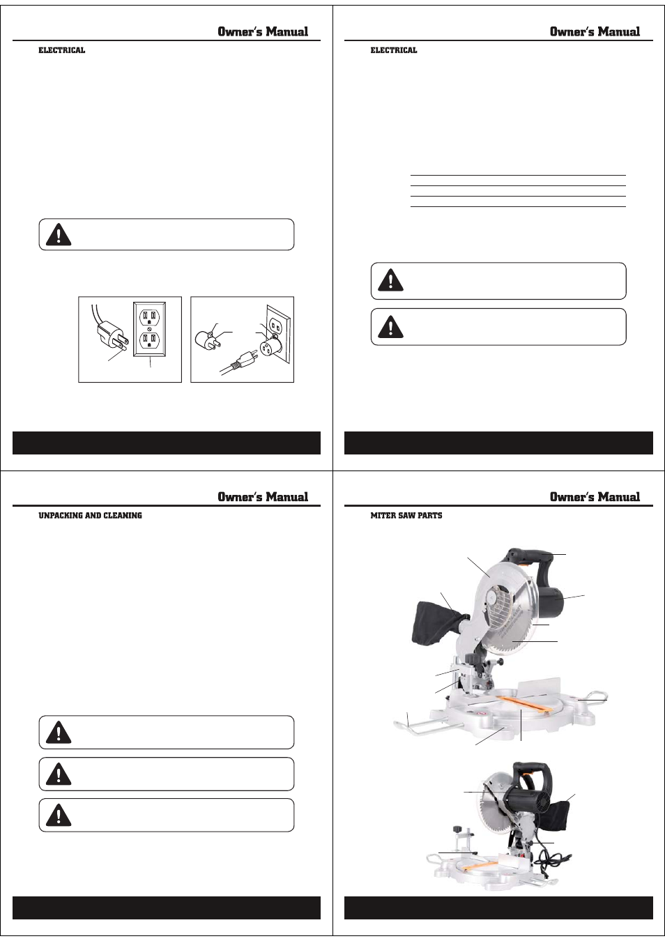
Before attempting to use this product, familiarize yourself with all operating
features and safety rules.
Upper Blade Guard
Dust Extraction Port
Bevel Lock Wheel
Work Clamp
Extension Bar
Bench Mounting Holes
Motor
Main Handle
Saw Blade
Base
Rotating Table
Lower Blade Guard
Table Lock Pin
Carbon Brush Cap
Head Lock Pin
Dust Bag