Specific safety rules and/or symbols symbols, Important safety instructions, Components – Steele Products SP-PB208 User Manual
Page 4
BEFORE USING THIS TOOL, YOU NEED TO BECOME FAMILIAR WITH ITS OPERATION. IF YOU
ARE UNSURE ABOUT THE OPERATION OF THE TOOL, OR HAVE ANY QUESTIONS ABOUT ITS
PROPER USE, CALL THE CUSTOMER SERVICE DEPARTMENT AT 1-888-896-6881.
FOLLOW THESE INSTRUCTIONS FOR SAFE HANDLING OF THE TOOL:
Always secure and support the work piece using clamps.Do not use your hands to hold the piece
in place.
Be sure your work area is clean and secure before turning the power switch into the“ON”position.
Be sure the area is free from all foreign material, nails, staples, or any other material.
Turn the drill“OFF”and unplug from the power source before making any changes or adjustments
to the drill.
Do not use solvents containing carbon tetrachloride, ammonia or acetone to clean the drill. Never
use gasoline,paint thinner,or other caustic chemicals that can damage the plastic parts of the tool.
Always use the appropriate safety gear when operating this drill. Including but not limited, to
goggles,dust mask or respirator. Always work in a well-ventilated area to reduce your exposure
to harmful chemicals and dust particles.
Keep hands away from the cutting area.
Do not reach under the work piece.
SPECIFIC SAFETY RULES AND/OR SYMBOLS
SYMBOLS
THE FOLLOWING SYMBOLS MAY BE USED ON YOUR TOOL. BE FAMILIAR WITH AND LEARN THE
SYMBOLS TO OPERATE THE TOOL SAFELY.
SYMBOL
NAME
DESCRIPTION
V
VOLTS
VOLTAGE (POTENTIAL)
A
AMPERES
CURRENT
HZ
HERTZ
FREQUENCY (CYCLES PER SECOND)
W
WATT
POWER
KG
KILOGRAMS
WEIGHT
ALTERNATING CURRENT
TYPE OF CURRENT
DIRECT CURRENT
TYPE OF CURRENT
ALTERNATING OR DIRECT CURRENT
TYPE OF CURRENT
EARTHING TERMINAL
GROUNDING TERMINAL
CLASS II CONSTRUCTION
DENOTES DOUBLE INSULATION
MIN
MINUTES
TIME
S
SECONDS
TIME
DIAMETER
SIZE OF DRILL BITS, GRINDING WHEELS, ETC.
NO LOAD SPEED
NO-LOAD ROTATIONAL SPEED
…/MIN
REVOLUTIONS PER MINUTE
REVOLUTIONS, SURFACE SPEED, STROKES, ETC. PER MINUTE
1,2,3…
RING SELECTOR SETTINGS
SPEED, TORQUE OR POSITION SETTINGS
IMPORTANT SAFETY INSTRUCTIONS
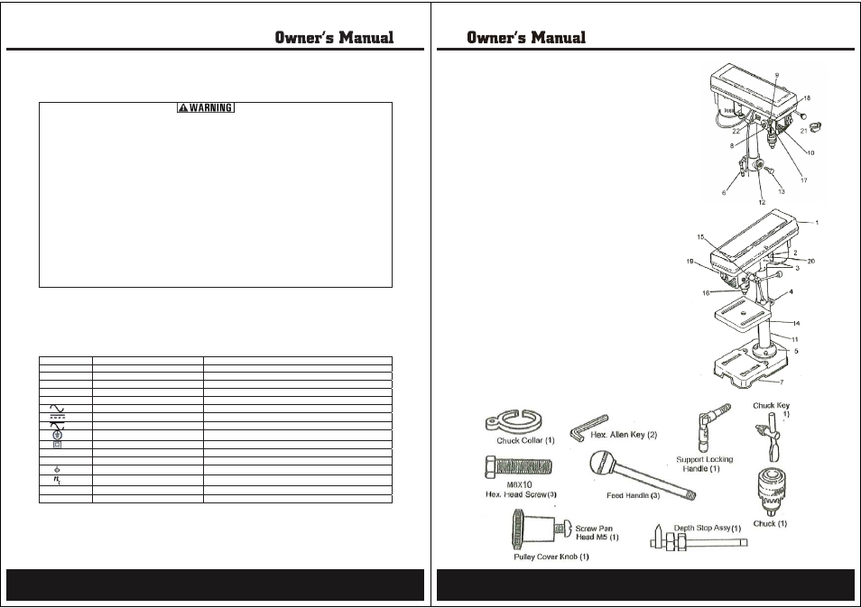
7
• 5 Speed Drill Head Assembly
• Table Assembly
• Base
• Column Assembly
• Assorted Loose Parts
COMPONENTS
1) Pulley Cover
2) Belt Tension Locking Screw
3) Head Lock Set Screws
4) Table Support
5) Column Support
6) Table Support Locking Handle
7) Base
8) Quill Spring Assembly
9) Pointer
10) Depth Scale
11) Column
12) Bevel Scale
13) Table Lock Set Screw
14) Table
15) Feed Handles
16) Chuck
17) Feed Stop Rod
18) Stop Nuts
19) Power Switch
20) Motor Stop
21) Chuck Collar
22) Laser Power Switch
ASSORTED LOOSE PARTS
PACKAGE CONTENTS
8