Philips 32PS55S User Manual
Page 25
25
VOL
75
⍀
VIDEO
L/
Mono
AUDIO
R
Monitor out
COMPONENT VIDEO INPUT
AV1 in
S-VIDEO
Y
Pb
Pr
75
⍀
VIDEO
L/
Mono
AUDIO
R
Monitor out
COMPONENT VIDEO INPUT
AV1 in
S-VIDEO
Y
Pb
Pr
S-VIDEO
OUT
OUT
OUT
L
R
AUDIO
VIDEO
COMP VIDEO
Y
Pb
Pr
2
4
6
5
1
1
2
3
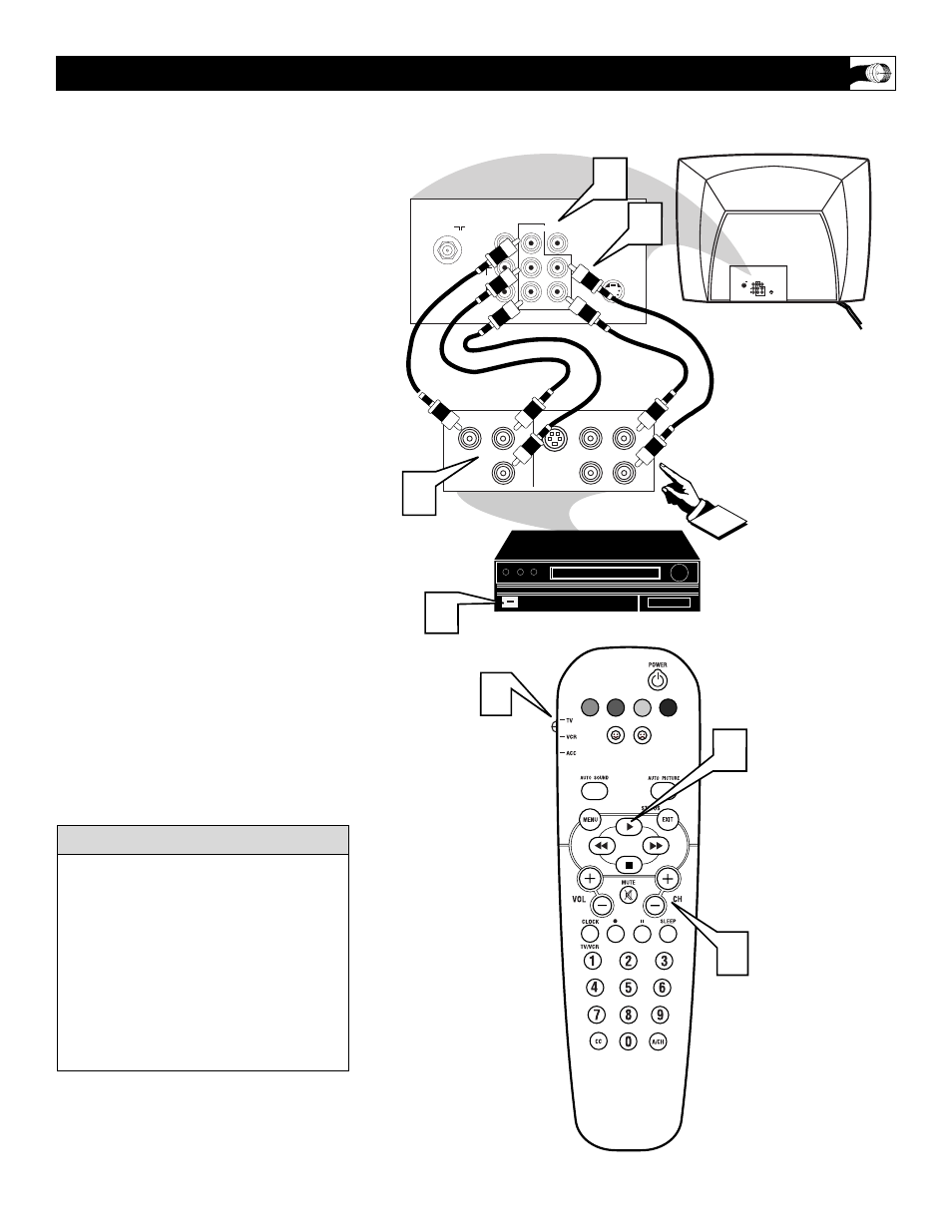
C
omponent Video inputs provide for the
highest possible color and picture resolu-
tion in the playback of digital signal source
material, such as with DVD players. The
color difference signals (Pb, Pr) and the lumi-
nance (Y) signal are connected and received
separately, which allows for improved color
bandwidth information (not possible when
using composite video or S-Video connec-
tions).
1
Connect the Component (Y, Pb, Pr)
Video OUT jacks from the DVD play-
er (or similar device) to the (Y, Pb, Pr)
in(put) jacks on the TV.
2
Connect the red and white AUDIO
CABLES to the Audio (left and right)
output jacks on the rear of the accesso-
ry device to the Audio (L and R) AV1
in(put) jacks on the TV.
3
Turn the TV and the DVD (or digital
accessory device) ON.
4
Press the CH + or – buttons to scroll
the available channels until AV1
appears in the upper left corner of the
TV screen.
5
Slide the TV/VCR/ACC Switch to
the ACC position.
6
Insert a DVD disc into the DVD player
and press the PLAY
ᮣ
button on the
remote.
U
SING THE
C
OMPONENT
V
IDEO
I
NPUT
J
ACKS
The description for the component video
connectors may differ depending on the
DVD player or accessory digital source
equipment used (for example, Y, Pb, Pr; Y,
B-Y, R-Y; Y, Cr, Cb). Although abbrevia-
tions and terms may vary, the letters b and r
stand for the blue and red color component
signal connectors, and Y indicates the lumi-
nance signal. Refer to your DVD or digital
accessory owner’s manual for definitions
and connection details.
H
ELPFUL
H
INT
AUDIO IN
(RED/WHITE)
COMPONENT
VIDEO CABLES
DVD, DBS OR SIMILAR
ACCESSORY DEVICE EQUIPPED
WITH COMPONENT VIDEO JACKS.
BACK OF TV