Burnham SM-6 User Manual
Page 18
18
Use the Trouble Shooting Guide (pages 19 to 21) to
assist in locating where a malfunction in the control
system is occurring.
4
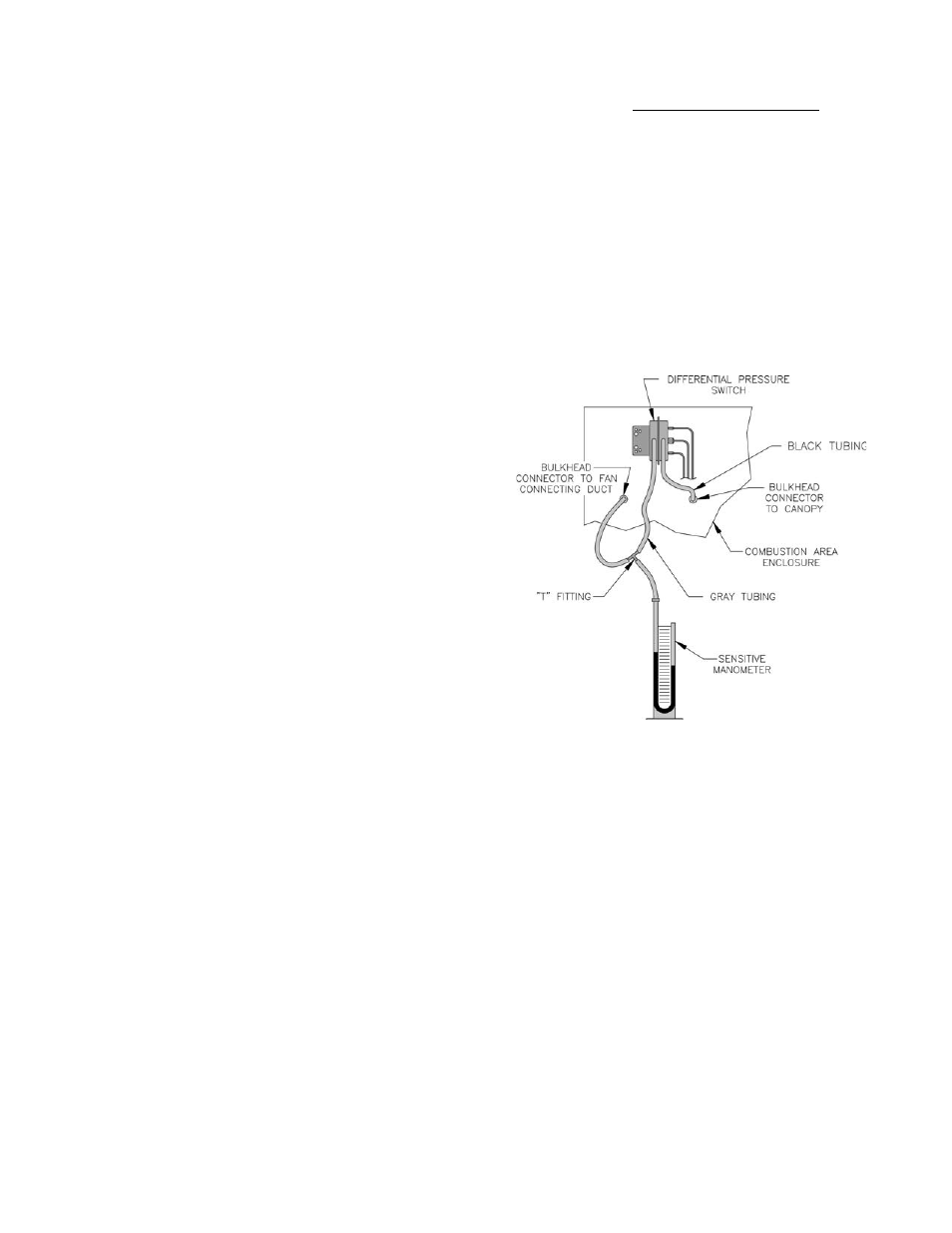
PROCEDURE FOR MEASURING FAN
DIFFERENTIAL PRESSURE (See Figure 13).
a. With boiler off, remove black silicone tubing from
low side of pressure switch.
b. With tee and ¼” aluminum stubs, connect
manometer as shown with additional tubing.
c. Start boiler and read differential pressure on
manometer. Should be -0.6” wc or greater (example
-0.7” wc).
d. Stop boiler, remove manometer and reconnect black
silicone tubing to duct.
5
CHECK GAS INPUT RATE TO BOILER
a. Input rate and maximum inlet pressure shown on
rating label must not be exceeded. Inlet pressure
must not be lower than minimum inlet pressure
shown on rating label.
b. All rate checks and all adjustments are to be made
while boiler is fi ring - all other appliances connected
to the same meter as the boiler must be off.
c. Water manometer or water column gauge should
be connected to a shutoff valve installed in the
1/8” pipe tapping in the gas valve - boiler off. By
installing gas valve up stream of manometer, gas
pressure can be introduced gradually - without
shutoff valve, surge of pressure when boiler is
turned on, could blow liquid out of manometer.
Replace plug in gas valve when rate check is
fi nished.
d. Approximate input - Adjust pressure regulator on
combination gas control so that manifold pressure is
equal to that shown on rating label. Determine what
TROUBLE SHOOTING
Figure 13
PROCEDURE FOR MEASURING FAN DIFFERENTIAL
PRESSURE
fl ow (cu. ft.) should be in 3 minutes using formula
below:
cu. ft. per = Btuh Input (from Rating Label)
3 min. = 20000
Clock gas meter for three (3) minutes using second
hand or stop watch.
For minor input changes readjust pressure regulator
on combination gas control. Increase or decrease
manifold pressure to obtain corresponding increase
or decrease in gas input.
Turning regulator adjusting screw clockwise
increases pressure. Counterclockwise rotation
decreases pressure. If it is necessary to increase
manifold pressure more than 0.3” of water to obtain
rated input, remove orifi ces and drill one size larger.
Reinstall and recheck input rate.