Liebherr LTM 1220-5.2 User Manual
Page 9
700
9
4
LTM 1220-5.2
LTM 1220-5.2
• Variable support basis
outriggers retracted
Support basis 5.5 m x 8.9 m
Support basis 8.3 m x 8.9 m
• Fix-mounted supporting pads with splash guard
• Supporting ram travel of up to 700 mm
• Level control of the outriggers, all-automatic push-button
crane levelling during the supporting procedure
• 2 x 9° lateral inclination of crane and crane superstructure
• Control panels at either side of the carrier with membrane
keyboard and electronic inclination indicator, push-buttons
for ENGINE/START/STOP and speed control are illuminated
and lockable
• Operation of the outrigger system in accordance with
accident-prevention legislation
• Illumination of the supporting area by 4 incorporated
projectors
Setting crane on outriggers –
quick, convenient and safe
• Modern, comfortable driver’s cab of high functionality and
convincing design, corrosion-resistant, sheet steel version,
cataphoretic dip-primed, front mounted on rubber shock
absorbers, rear cushioned hydraulically, internal sound and
heat absorbing panelling
• Safety glass all-round, greenish tinted front and side windows
for heat absorption, electric window lifters
• Arrangement of the control elements and displays according
to ergonomical aspects for safe and convenient handling
during continuous operation
• Digital display and keyboard units interconnected with the
functional blocks by data bus technology
• Driver’s seat cushioned pneumatically, with pneumatic lumber
support, headrest
• Steering wheel adjustable in height and inclination
• Heatable and electrically adjustable rear mirrors
• Safety belts for driver and co-driver
• 3 windscreen wipers with automatic wipe/wash system and
intermittent control
• Delayed switch-off of the interior lights
• Various racks and stackers
• Radio preparation
Comfortable driver’s cab
of high functionality
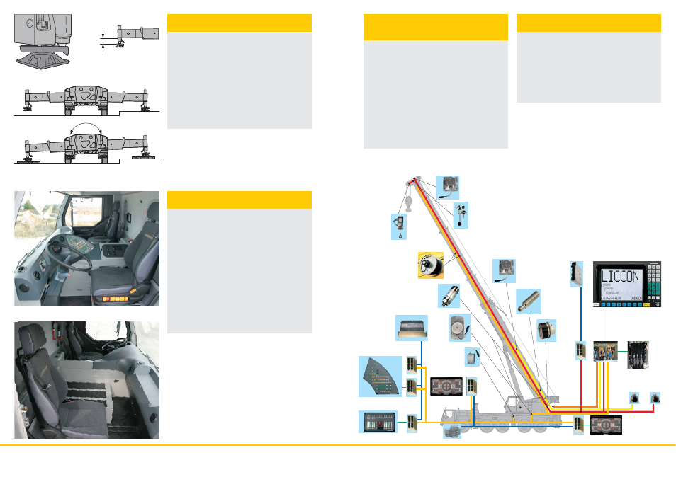
The Liebherr mobile cranes are entirely equipped with data
bus transfer systems. The digital system is the basis for the
data bus. It permits the transfer of a multitude of information
almost parallel and faultless via one only cable. Liebherr has
developed its own system bus (LSB) which corresponds to
the manifold requirements in respect to all possible mobile
crane operations. All important electrical and electronical
components on the superstructure, such as length sensors,
angle sensors, load cells, proximity switches, master switches
and hoist limit switch are equipped with their own
microprocessors and communicate via various data bus
networks. The keyboard and display units, the outrigger control
as well as the engine and transmission control on the vehicle
are intelligent function blocks and equipped with bus interfaces.
A continuous self-test of the sensors during operation
guarantees a high functional reliability. The internetworking of
the LICCON computer system with the system bus establishes
entirely new and comprehensive diagnostic facilities in respect
to the crane.
Data bus technique
revolutionises the
crane electric system
• Reduction of the operating costs due to a modern engine
and transmission management (CAN bus system); increased
economy due to improved endurance of the individual units
• Improved reliability due to a considerably reduced number
of electrical cables and contacts
• A continuous self-test of the „intelligent sensors“ guarantees
a maximum of reliability
• Comprehensive diagnostic facilities - quick error detection
• Self-manufactured bus systems, specially adapted to the
requirements of a mobile crane
• The data bus technique increases the comfort and safety
during driving and crane operation
The advantages of the
data bus technique at a glance